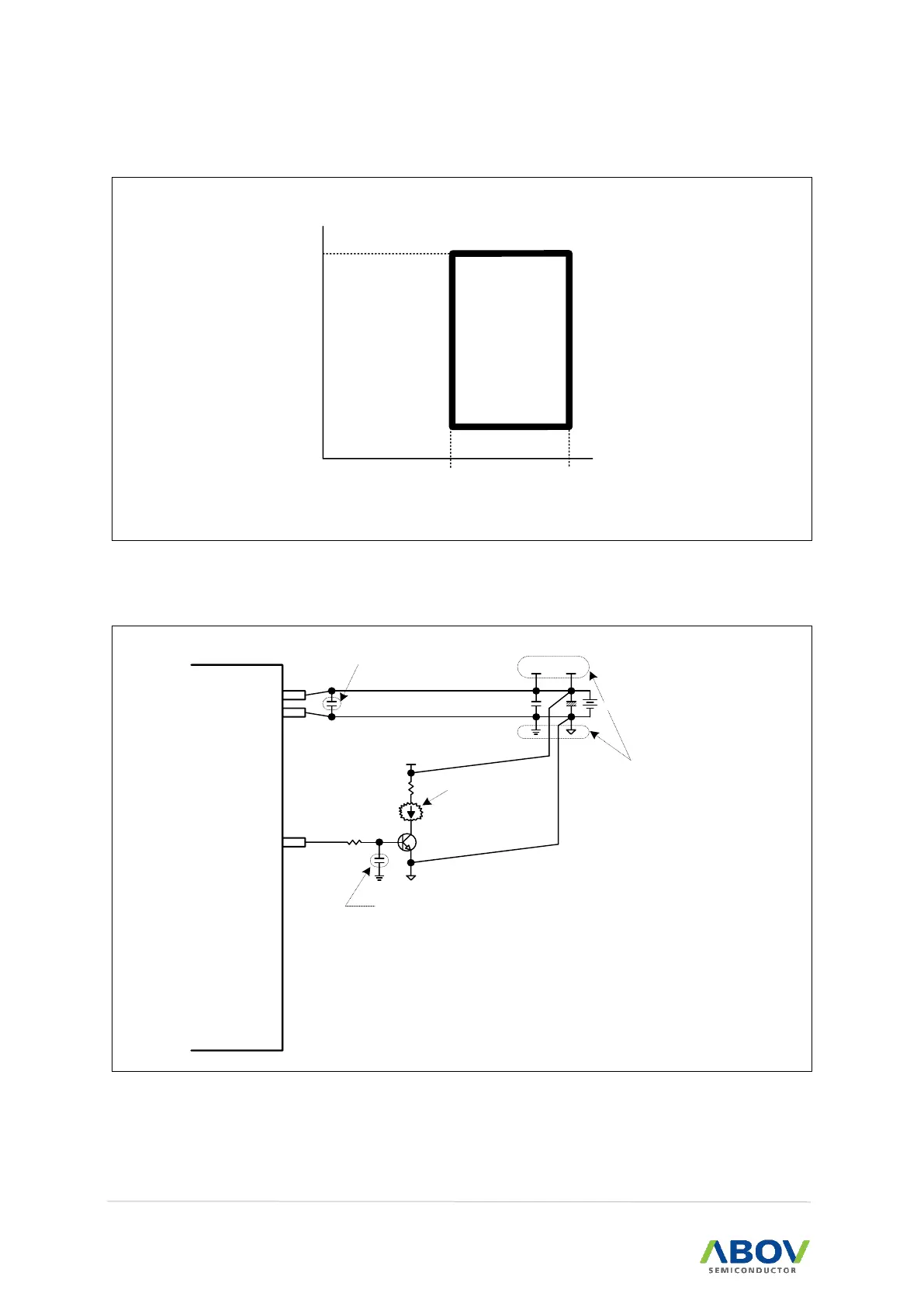
EasyManuals Logo

Abov MC97F6108A User Manual

Default Icon
256 pages
To Next Page IconTo Next Page
To Previous Page IconTo Previous Page
Page #232 background imageLoading...
Page #232 background image
20. Electrical characteristics MC97F6108A User’s manual
232
20.20 Operating voltage range
2.7 5.5
16.0MHz
(fIRC= 16MHz)
Supply voltage (V)
Figure 115. Operating Voltage Range
20.21 Recommended circuit and layout
{ }
MC97F6108
A
I/O
VSS
VDD
High-Current Part
Infrared LED,
FND(7-Segment),
,,,,,
etc
{ }
0.01uF
VCC
0.1uF
This 0.1uF capacitor should be within
1cm from the VDD pin of MCU on the
PCB layout.
{ }
This 0.01uF capacitor is alternatively
for noise immunity.
+
0.1uF
VDD VCC
{ }
The MCU power line (VDD and VSS)
should be separated from the high-
current part at a DC power node on
the PCB layout.
DC Power
Figure 116. Recommended Voltage Range

Table of Contents

Questions and Answers:

Question and Answer IconNeed help?

Do you have a question about the Abov MC97F6108A and is the answer not in the manual?

Abov MC97F6108A Specifications

General IconGeneral
BrandAbov
ModelMC97F6108A
CategoryMicrocontrollers
LanguageEnglish

Related product manuals