EasyManua.ls Logo

Abov MC97F6108A - IDLE Mode Operation

Default Icon
256 pages
To Next Page IconTo Next Page
To Previous Page IconTo Previous Page
Loading...
MC97F6108A User’s manual 17. Power down operation
185
17.2 IDLE mode
Power control register is set to β€˜01h’ to enter into IDLE mode. In IDLE mode, internal oscillation circuits
remain active. Oscillation continues and peripherals are operated normally, but CPU stops.
It is released by reset or an interrupt. To be released by an interrupt, the interrupt should be enabled
before IDLE mode. If using a reset, because the device is initialized, registers become to have reset
values.
Figure 82. IDLE Mode Release Timing by an External Interrupt
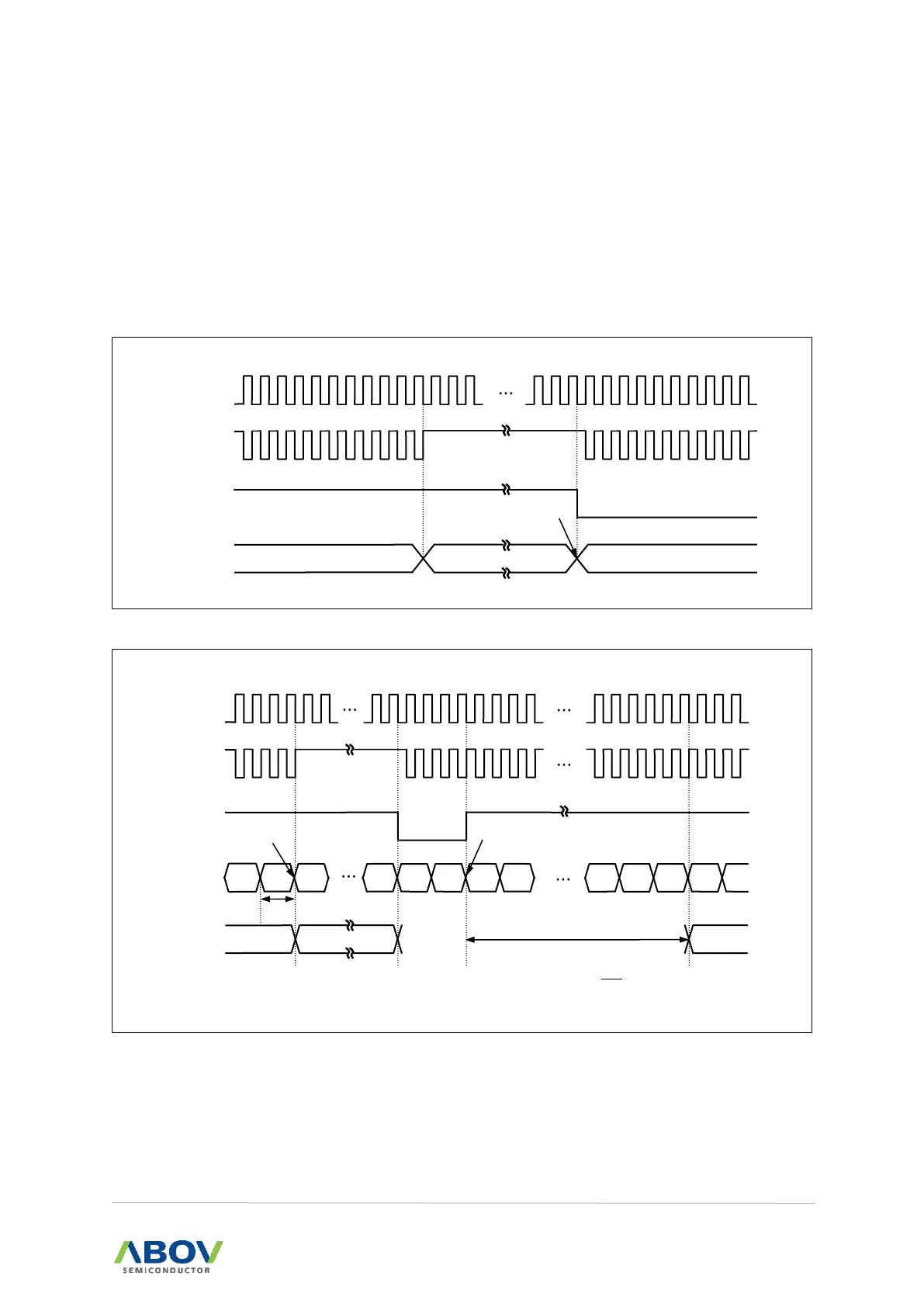
Figure 83. IDLE Mode Release Timing by an RESETB
Example
MOV PCON, #0000_0001b ; The Setting of IDLE mode, Set the bit of STOP and
IDLE Control register (PCON)
External
Interrupt
OSC
Normal Operation
Release
CPU Clock
Stand-by Mode
Normal Operation
OSC
CPU Clock
RESETB
Normal Operation
BIT Counter
IDLE Mode
Normal Operation
Release
Set PCON
to 01
Clear & Start
TST = 32.7ms @ 16MHz
𝐓𝐒𝐓 =
𝟏
πŸπŽπ’π‚
Γ— πŸπŸŽπŸ’πŸ– Γ— πŸπŸ“πŸ”
m-2
m-1
m
n
0
0
0
1
FD
FE
FF
0
1
T
OSC
= 1/f
OSC
f
OSC
= 16MHz
BCK[1:0] in BCCR = 00
B
BPD[2:0] in BCCR = 111
B
2048 T
OSC

Table of Contents

Related product manuals