10.4 16-bit PWM mode
Timer0/1/2/3 has a PWM (pulse Width Modulation) function. In PWM mode, 16-bit resolution PWM
wave form is output through TxO/PWMx pin. This pin should be configured as a PWM output by set
TX_PE to ‘1’. The PWM output mode is determined by the PWMxPRH, PWMxPRL, PWMxDRH and
PWMxDRL. And you should configure PWMxE bit to “1” in TxCR register before write to PWM registers.
PWM Period = ( {PWMxPRH, PWMxPRL} + 1 ) x Timer0/1/2/3 Clock Period
PWM Duty = ( {PWMxDRH, PWMxDRL} + 1) x Timer0/1/2/3 Clock Period
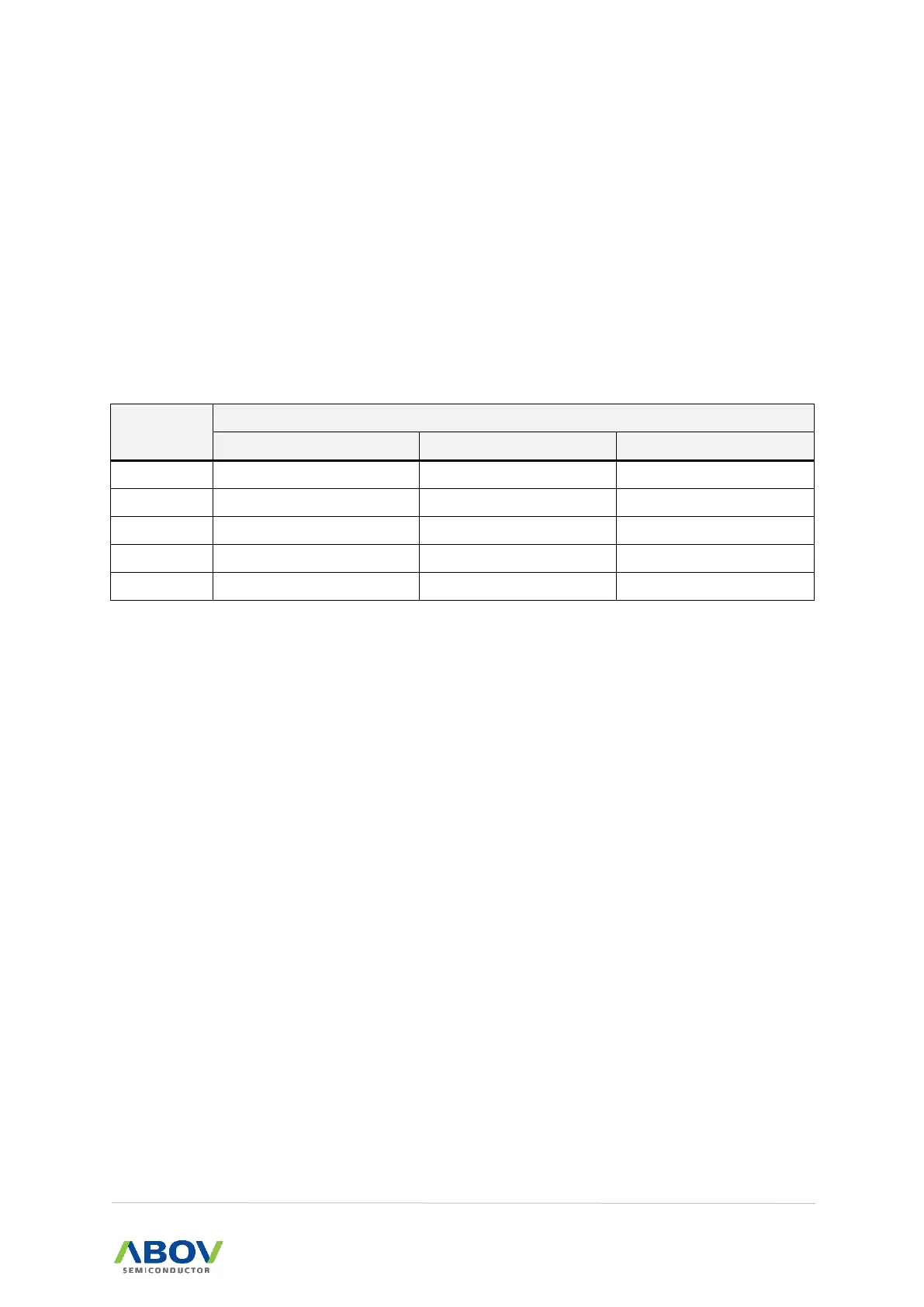
Table 14. PWM Frequency vs. Resolution at 16MHz
In PWM mode, the duty value and counter matching enables the period value and counter comparison.
After counter and the period value matching, counter restarts. If the duty value is set the same to the
period value, counter doesn't restart after the duty value and counter matching. It is highly
recommended that the duty value is not set the same value with the period value.
The output of the same PWM period and duty shows in
POL bit in TxCR register decides the polarity of duty cycle.