MC97F6108A User’s manual 10. Timer0/1/2/3
10.2 16-bit timer/counter mode
In the 16-bit timer/counter mode of timer0/1/2/3, If the value of TxH/TxL and the value of TxDRH/TxDRL
are matched, the square wave form is output through TxO/PWMx port. The output is 50:50 of duty
square wave, the frequency is following
)1(Value Prescaler2
Frequency Clock Timer
+
=
TxDR
COMP
f
f
COMP
is timer output frequency and TxDR is the 16 bits value of TxDRH/TxDRL.
To export the compare output through TxO/PWMx, Tx_PE bit in the TxCR1 register must set to ‘1’.
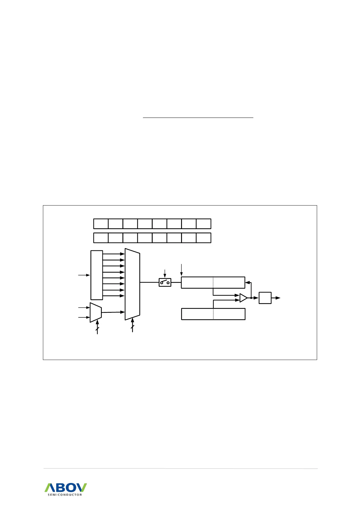
16-bit timer/counter mode of timer0/1/2/3 is selected by control registers as shown in Figure 27.
When TxH/TxL are read, TxL should be read first. Because when TxL is read, TxH is captured to buffer,
and when TxH is read, the captured value of TxH is read.
P
R
E
S
C
A
L
E
R
÷ 1
÷ 4
÷ 8
÷ 16
÷ 64
÷ 256
÷ 1024
÷ 2048
MUX
TxH(8-bit) TxL(8-bit)
16-bit Counter
TxST
TxEN
4
ECEN,TxCK[2:0]
f
X
TxIF
Timerx
Interrupt
-
-
TxIN[2] TxIN[1] TxIN[0] ECEN TxPE POL
TxCR
TxCR1
ADDRESS : B2
H
, BA
H
, C2
H
, CA
H
INITIAL VALUE : 0000_0000
b
ADDRESS : B3
H
, BB
H
, C3
H
, CB
H
INITIAL VALUE : --00_0000
b
comparator
TxDRH(8-bit) TxDRL(8-bit)
TxEN
PWMxE
CAPx TxCK2 TxCK1 TxCK0 TxCN TxST
TxEC0
TxIN = 000
TxEC1
TxIN = 001
3
TxIN[2:0]
ECEN = 1
Figure 27. 16-bit Timer/Counter Mode of Timer0/1/2/3