EasyManuals Logo

Abov MC97F6108A User Manual

Default Icon
256 pages
To Next Page IconTo Next Page
To Previous Page IconTo Previous Page
Page #143 background imageLoading...
Page #143 background image
MC97F6108A User’s manual 14. 12-bit AD Converter (ADC)
143
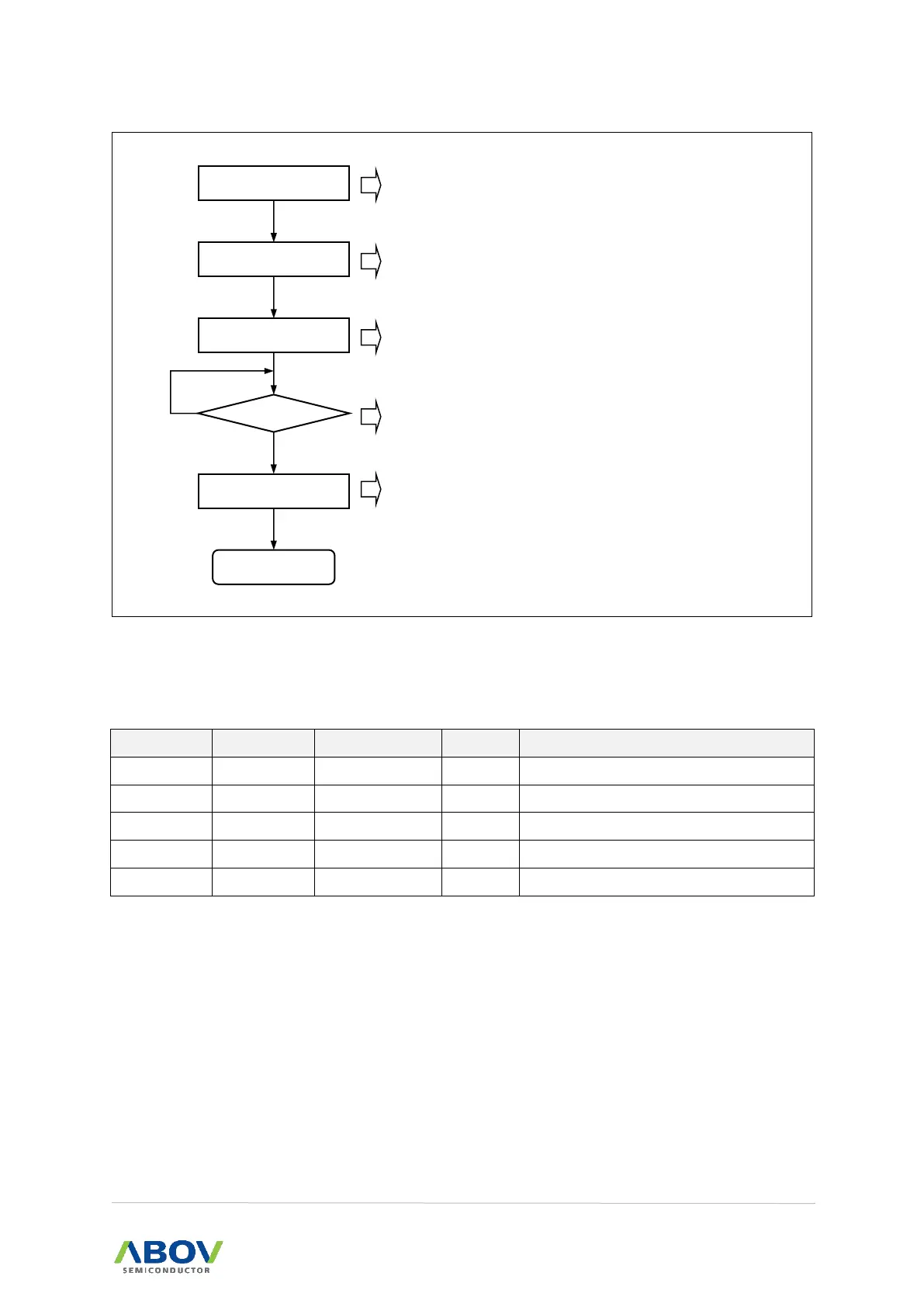
Figure 65. ADC Operation Flow Sequence
14.4 Register map
Table 19. ADC Register Map
Name
Address
Direction
Default
Description
ADCM
95H
R/W
8FH
A/D Converter Mode Register
ADCRL
96H
R
xxH
A/D Converter Data Low Register
ADCRH
97H
R
xxH
A/D Converter Data High Register
ADCM1
96H
R/W(STBY=1)
01H
A/D Converter Mode 1 Register
ADCM1
96H
R/W(STBY=0)
01H
A/D Converter Mode 1 Register
SET ADCM1
SET ADCM
AFLAG = 1?
Converting START
READ ADCRH/L
ADC END
Select ADC Clock & Data Align Bit.
ADC enable & Select AN Input Channel.
Start ADC Conversion.
If Conversion is completed, AFLG is set “1” and ADC
interrupt is occurred.
After Conversion is completed, read ADCRH and ADCRL.
Y
N

Table of Contents

Questions and Answers:

Question and Answer IconNeed help?

Do you have a question about the Abov MC97F6108A and is the answer not in the manual?

Abov MC97F6108A Specifications

General IconGeneral
BrandAbov
ModelMC97F6108A
CategoryMicrocontrollers
LanguageEnglish

Related product manuals