Installation and Commissioning Guide
Split Tri-Capacity
47
Installation and Commissioning Guide 500-700 Tri-Capacity Split Ducted
Doc. No.0525-098 Ver. 2 210330
NOTES
• Commissioning of the EC Fans should be carried out by a qualified technician only.
• Make sure that all instructions are followed accordingly.
• Ensure that connecting duct work and air filters are installed accordingly.
1. Refer to Section 27 for Fan Performance Data or the Fan Curve specific to your air conditioner.
2. Determine the Required Fan Speed (%) which matches your Airflow and External Static Pressure requirements using either
the Fan Performance Data or the Fan Curve.
Example:
Unit Model: CAY620T / EVY620T
Airflow: 3200 l/s
External Static Press: 100 Pa
Required Fan Speed: 62.9%
The Required Fan Speed shall be used with one of the applicable method below.
METHOD SECTION
CP05 Control Interface 18.02.01
External 0-10VDC Input (Outdoor Unit) 18.02.02
Indoor Board Voltage Adjustment (Potentiometer)* 18.02.03
*NOTE
Indoor Board Voltage Adjustment (Potentiometer) is recommended only for Indoor Fan Commissioning prior to Outdoor
installation
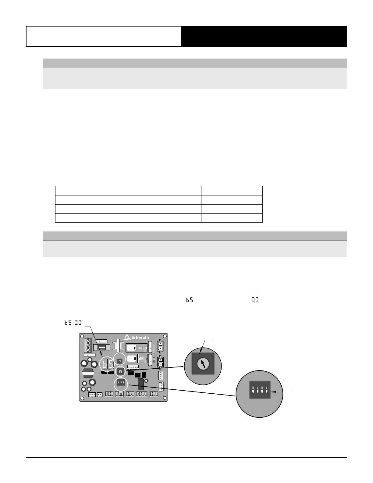
18.02.01. Fan Speed Set Through CP05 Control Interface
Before performing the Indoor fan commissioning procedures below, make sure that the Unit model Set Dial on
the indoor board is set to F and the DIP switches are all OFF (See illustration below).
LED FAN STATUS Display will toggle between
(Interface Control)
and
(0-10V Out Speed Control)
.
1 2 3 4
ON
PWM1
A N
G N A
A N
PWM2
A B
485 OUTDOOR
COM NC NO
AUX OUTPUT
10V 0V
0 - 10V OUT
10V 0V
0 - 10V IN
DIP
SWITCH
POT
ADJUST
UNIT SET
COM DN
FAULT INPUT
COIL TEMPAUX SENSOR
0
1
9
5
D
2
A
6
E
3
B
7
F
4
C
8
(CIB01)
COMMERCIAL INDOOR BOARD
LED FAN STATUS
DISPLAY
SET TO F
0
1
9
5
D
2
A
6
E
3
B
7
F
4
C
8
UNIT SET
MAKE SURE ALL
DIP SWITCHES
ARE OFF FOR
INTERFACE
OPERATION
1 2 3 4
ON
DIP
SWITCH
UNIT SET