50
Installation and Commissioning Guide 500-700 Tri-Capacity Split Ducted
Doc. No.0525-098 Ver. 2 210330
Installation and Commissioning Guide
Split Tri-Capacity
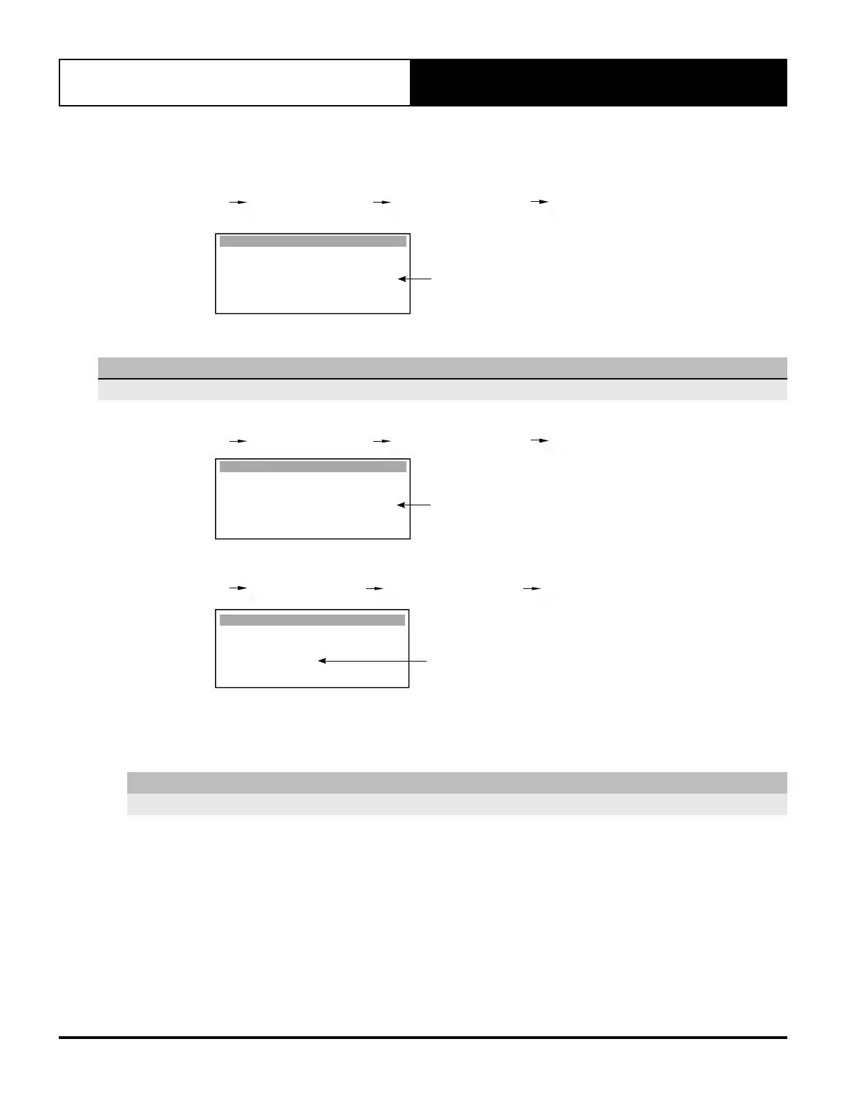
Now fan speed is set through TERM 13 (Multi input 1), input 0-10VDC, fan speed is maintained within the
minimum and maximum speed as shown on screen Gfc4.
On screen Gfc4, if required, adjust the Supply Fan Maximum Speed to your applications maximum fan speed.
G. Service Gfc. Service Settings Gfc. Thermoregulation Gfc4. Thermoregulat. (Supply Fan
Settings).
% Maximum Fan Speed
Thermoregulat. Gfc4
Supply Fan
Minimum speed: 49.0%
Medium speed: 71.9%
Maximum speed: 90.0%
Supply Fan Temp.
Minimum Temp. 5.0
o
C
Maximum Temp. 50.0
o
C
This will limit the fan speed if the 0-10VDC input is outside this range.
NOTE
Minimum and Maximum fan speeds are factory default settings.
Ensure that One Speed fan is set to Yes
G. Service Gfc. Service Settings Gfc. Thermoregulation Gfc5. Thermoregulat.
YES
Thermoregulat. Gfc5
Supply fan Gen. 3 :
Supply fan Contin :
Cycle on de-ice :
One Speed fan :
Supply fan Run on :
Heat start delay :
No
Yes
Yes
Yes
30s
20s
Set Supply Fan Control to EXTERNAL via Gfc11
G. Service Gf. Service settings Gfc. Thermoregulation Gfc11. S. Configuration
EXTERNAL
S. Conguration Gfc11
Unit control mode :
EXTERNAL INPUT
Supply Fan Control :
EXTERNAL
Select Wall Control :
SINGLE CL01
Go to section 18.03 for compressor configuration procedure.
18.02.03. Stand Alone Mode Via Indoor Board Voltage Adjustment (Potentiometer)
NOTE
Recommended only for Indoor Fan Commissioning prior to Outdoor Unit installation.
Make sure that the Unit Set Dial on the CIB01 is set to correspond to your unit model. (Please refer to CIB01 Make sure that the Unit Set Dial on the CIB01 is set to correspond to your unit model. (Please refer to CIB01
Speed Range and Unit Set Dial Position tables on the next page).Speed Range and Unit Set Dial Position tables on the next page).
1. Locate the CIB01 Fan Control by undoing the cover of the Indoor Unit’s electrical box.
2. Turn - ON the unit through the Control Interface.