112100RPM Rev0
(OsmoPRO Service Manual
Page 4 of 5
17. Place the Timing Belt onto the Pulley
and loosely mount the replacement
Turntable Motor to the Turntable Motor
Mounting Plate with the four screws and
washers.
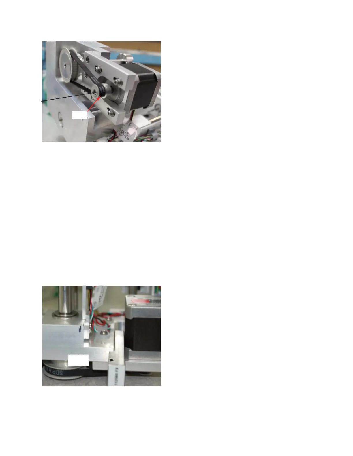
18. To set the proper tension on the Timing
Belt, place the Spacing Fixture
(112060FX) between the Osmometer
Module Mounting Base and the side of
the Turntable Motor. Fully tighten the
four screws that were used to mount the
motor to the Turntable Mounting Plate
and then remove the Spacing Fixture
(
Figure 11).
19. Secure the Turntable Motor’s Wire Leads
with the Cable Clamp shown in Figure 8.
20. Mount the Osmometer Module to the
Osmometer Module Mounting Bracket
using the four socket head cap screws
and washers.
21. Secure the SPG & BPG Ring Terminals
to the side of the Osmometer Module
Mounting Bracket using a hex nut and
washer.
22. Slide the Osmometer Module into the
instrument, and mount the Osmometer
Module Mounting Bracket to the Chassis
with the four socket head cap screws and
washers.
23. Slide the Power Supply & Controls
Assembly into the Base Assembly.
24. Secure the Power Supply & Controls
Assembly to the rear of the Chassis with
the two screws.
25. Rest the instrument on its back side.
Secure the Power Supply & Controls
Assembly to the bottom of the Chassis
using the two screws. Return the instru-
ment to the upright position.
26. Pair the following Connectors on the
Cooling System Harness to their mating
Connectors: A1, A2, A3, & A4.
27. Attach the following Connectors on the
Motor/Sensor Cable Harness to their cor-
responding Connectors: B1, B2, B3, B4,
B6, B7, B8, B9 & B10.
28. Plug the C10 and C11 Connectors into
the Control PCB.
29. Affix the C3G Ring Terminal to the side
of the Power Supply & Controls
Assembly using a screw. Plug the C3
Connector into the Control PCB.
Figure 11
Figure 10
Spacing
Fixture
Pulley
Turntable
Motor Shaft