6. Disconnect the following Connectors on
the Cooling System Harness from their
mating Connectors: A1, A2, A3 & A4.
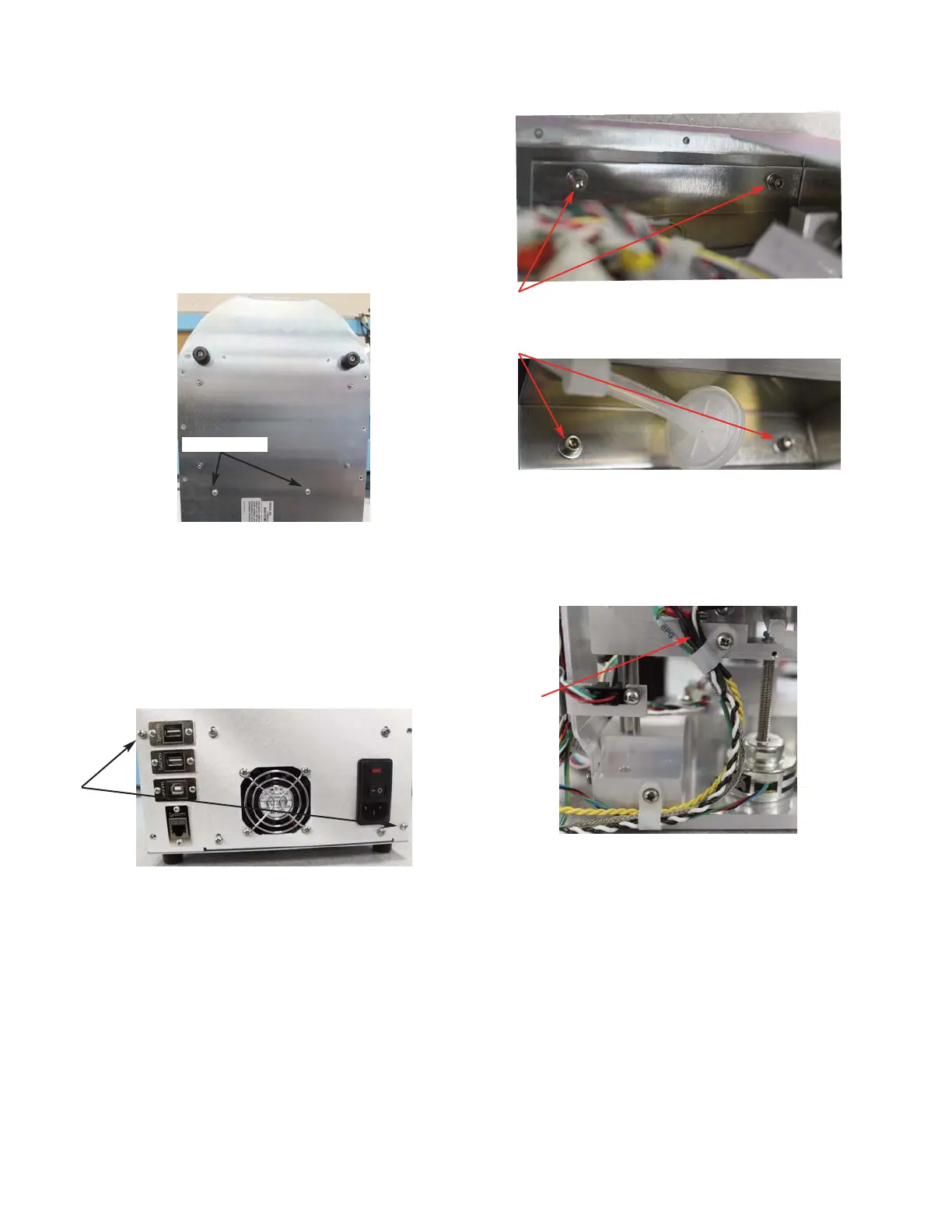
7. Rest the instrument on its back side.
Remove the two screws that secure the
Power Supply & Controls Assembly to
the bottom of the Chassis (
Figure 3).
8. Place the instrument in the upright posi-
tion. Remove the two screws that secure
the Power Supply & Controls Assembly
to the rear of the Chassis (
Figure 4).
9. Slide the Power Supply & Controls
Assembly out of the Base Assembly.
10. Remove the four socket head cap screws
and washers that mount the Osmometer
Module Mounting Bracket to the Chassis.
Carefully, slide the Osmometer Module
out of the instrument (
Figure 5A & Figure
5B).
11. Remove the Block Motor’s wire leads
from the Cable Clamps (Figure 6).
12. Remove the Drain Tube Adapter by loos-
ening the two set-screws (
Figure 7).
13. Remove the hex nut and washer that
secures the Block Motor’s Lead-Screw to
the top of the Sample Well Mounting
Block (
Figure 8).
Figure 3
Figure 4
Figure 5B
Figure 5A
Figure 6
112102RPM Rev0
(OsmoPRO Service Manual)
Page 2 of 4
Two Screws
Two Screws
Four
Socket
Head Cap
Screws
Wire Leads