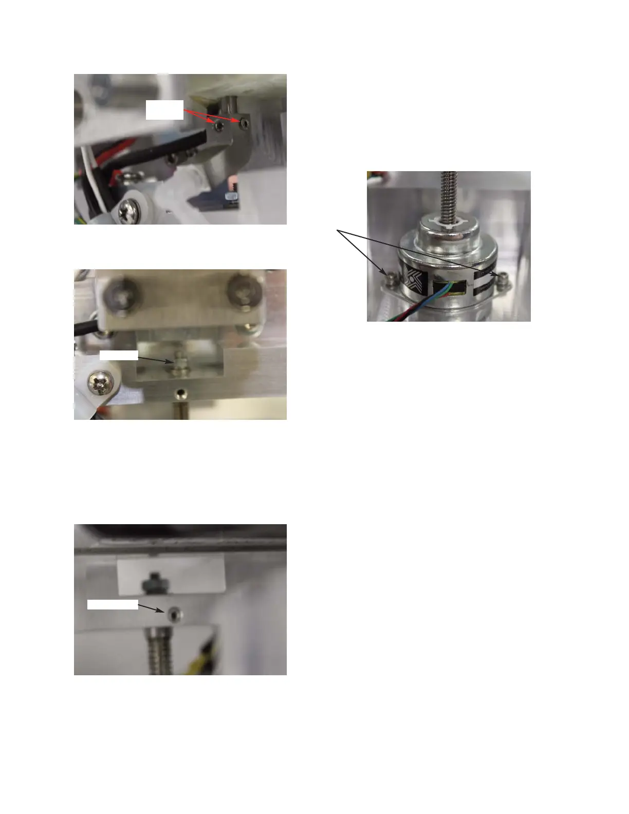
14. Remove the two set-screws located on
the sides of the Sample Well Mounting
Block (
Figure 9).
15. Remove the two socket head cap screws
and washers that mount the Block Motor
to the Osmometer Module Mounting
Base. Manually raise the Sample Well
Mounting Block and remove the Block
Motor (
Figure 10).
16. Mount the replacement Block Motor to
the Osmometer Module Mounting Base
using the two socket head cap screws and
washers.
17. Lower the Sample Well Mounting Block
until the Adaptor located on the end of
the Block Motor’s Lead-Screw is inserted
into the mounting block and the
Adapter’s threads are extending beyond
the top of it. Secure, but do not fully
tighten, the Adapter’s threads using the
hex nut and washers.
18. Secure the Block Motor’s Adapter to the
Sample Well Mounting Block using the
two set-screws.
19. Tighten the hex nut used to secure the
Adapter’s threads. If the Block Motor’s
Lead-Screw turns as this is being done,
then the two set-screws are not sufficient-
ly tightened.
Figure 10
112102RPM Rev0
(OsmoPRO Service Manual)
Page 3 of 4
Figure 7
Figure 8
Figure 9
Two Set
Screws
Hex Nut
Set Screw
Two
Socket
Head Cap
Screws