20. Manually raise and lower the Sample
Well Mounting Block several times in
order to verify that there is no binding,
etc.
21. Reinstall the Drain Tube Adapter using
the two set-screws.
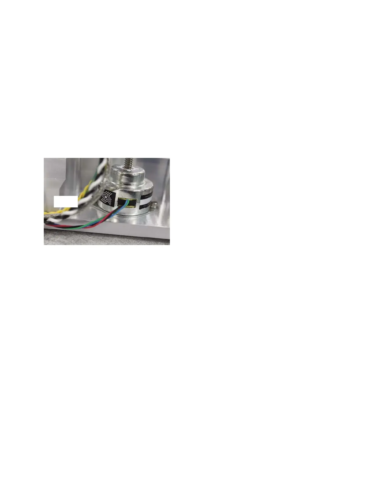
22. Secure the Block Motor’s wire leads
using the Cable Clamp shown in Figure
6. Be sure that there is a service loop
between the body of the Motor and the
Cable Clamp (
Figure 11).
23. Slide the Osmometer Module into the
instrument, and mount the Osmometer
Module Mounting Bracket to the Chassis
using the four socket head cap screws
and washers.
24. Slide the Power Supply & Controls
Assembly into the Base Assembly.
25. Secure the Power Supply & Controls
Assembly to the rear of the Chassis with
the two screws.
26. Rest the instrument on its back side.
Secure the Power Supply & Controls
Assembly to the bottom of the Chassis
with the two screws. Return the instru-
ment to the upright position.
27. Attach the following Connectors on the
Cooling System Harness to their corre-
sponding Connectors: A1, A2, A3, &
A4.
28. Pair the following Connectors on the
Motor/Sensor Cable Harness with their
mating Connectors: B1, B2, B3, B4, B6,
B7, B8, B9, & B10.
29. Plug the C10 and C11 Connectors into
the Control PCB.
30. Affix the C3G Ring Terminal to the side
of the Power Supply & Controls
Assembly with a screw. Plug the C3
Connector into the Control PCB.
31. Secure the C10 Sample Probe Cable and
the C11 Block Probe Cable to the side of
the Power Supply & Controls Assembly
with a Cable Clamp and a screw.
32. Reverse steps one through twelve of the
General Disassembly Instructions to re-
assemble the instrument.
112102RPM Rev0
(OsmoPRO Service Manual)
Page 4 of 4
Figure 11
Service
Loop