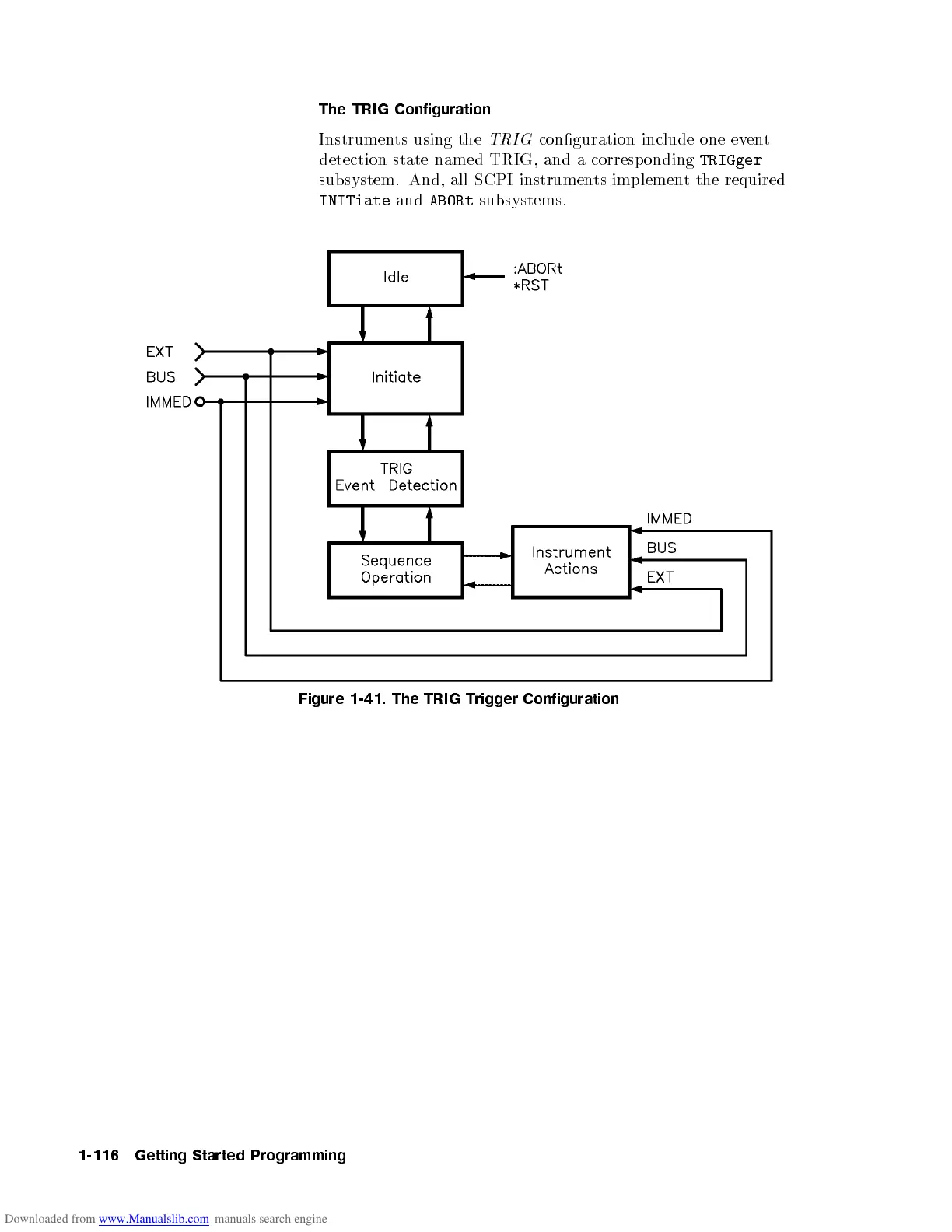
The TRIG Configuration
Instruments using the
TRIG
conguration include one event
detection state named TRIG, and a corresponding
TRIGger
subsystem. And, all SCPI instruments implement the required
INITiate
and
ABORt
subsystems.
Figure 1-41. The TRIG Trigger Configuration
1-116 Getting Started Programming

 Loading...


