NNNNNNNNNNNNNNNNNNNNNNNNNNNNNNNNNNN
Fltness Menu
When user atness correction is enabled, the sum of the two arrays
pro duces the 1601 reference voltages for the ALC system.
Figure F-3. The Sources of ALC Calibration Correction Data
If the correction frequency span is only a subset of the start/stop
frequency span set on the source, no corrections are applied to the
portion of the sweep that is outside the correction frequency span.
The following example illustrates how the data is distributed within
the user atness correction array.
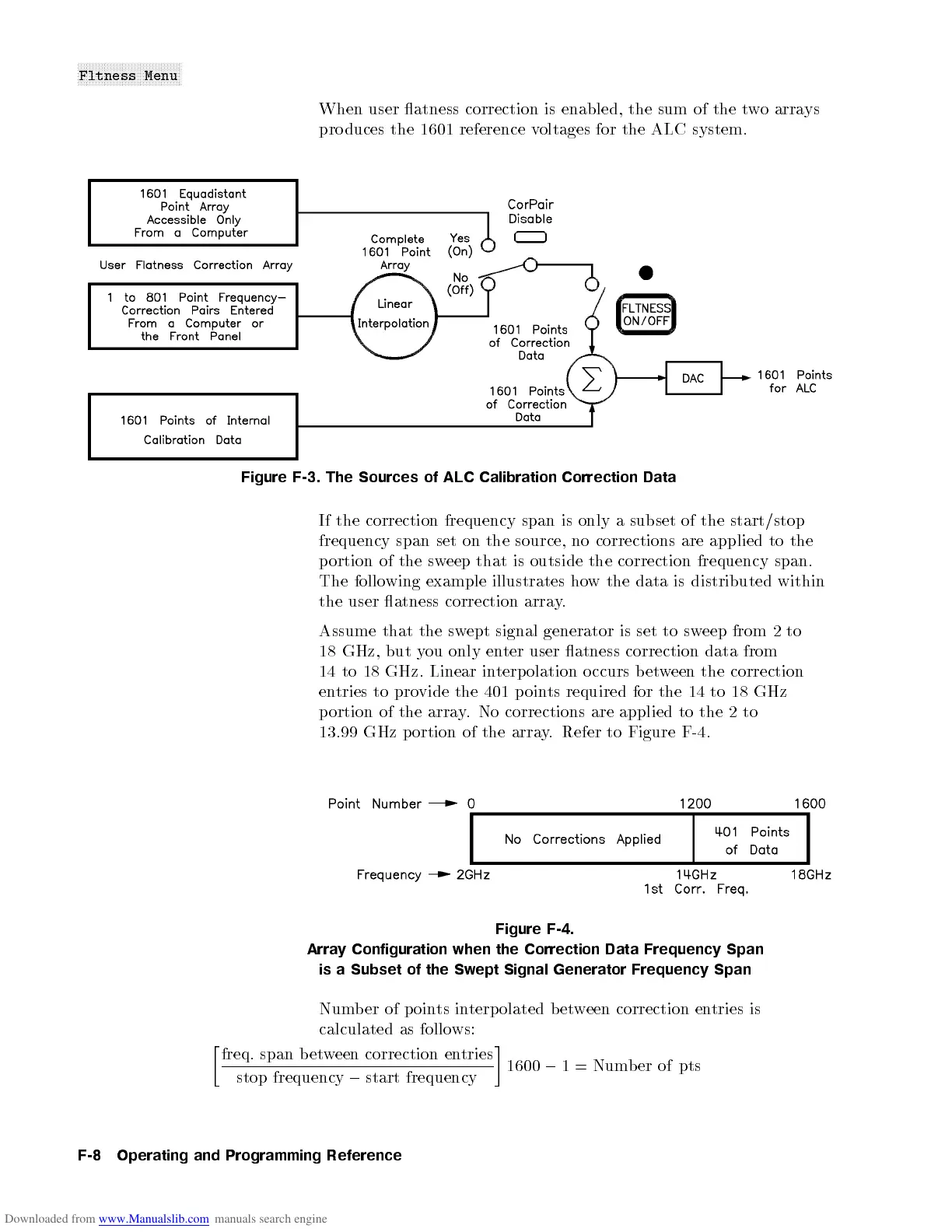
Assume that the swept signal generator is set to sweep from 2 to
18 GHz, but you only enter user atness correction data from
14 to 18 GHz. Linear interpolation o ccurs between the correction
entries to provide the 401 p oints required for the 14 to 18 GHz
portion of the array. No corrections are applied to the 2 to
13.99 GHz p ortion of the array. Refer to Figure F-4.
Figure F-4.
Array Configuration when the Correction Data Frequency Span
is a Subset of the Swept Signal Generator Frequency Span
Numb er of points interpolated b etween correction entries is
calculated as follows:
freq
:
span between correction entries
stop frequency
0
start frequency
1600
0
1 = Number of pts
F-8 Operating and Programming Reference

 Loading...


