NNNNNNNNNNNNNNNNNNNNNNNNNNNNNNNNNNN
Fltness Menu
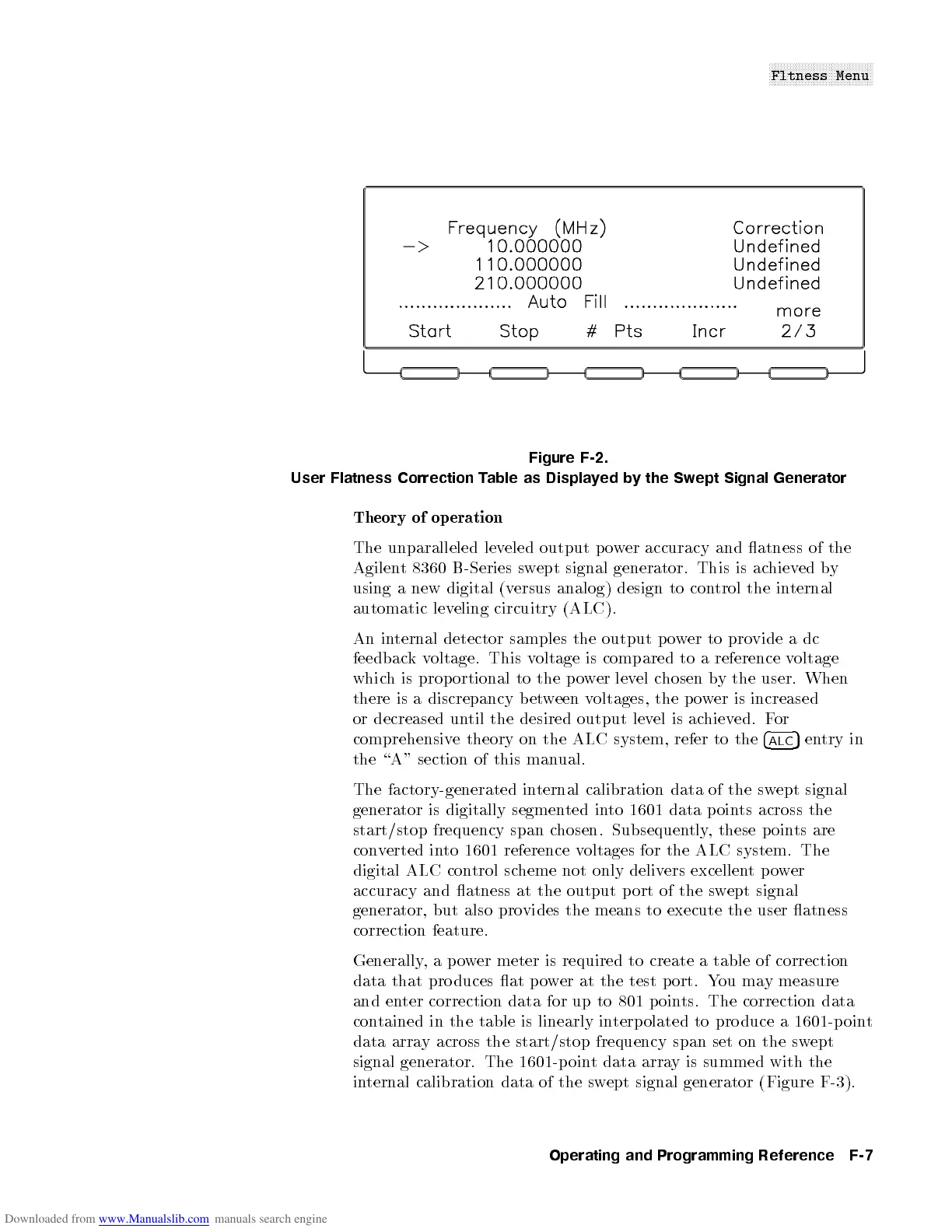
Figure F-2.
User Flatness Correction Table as Displayed by the Swept Signal Generator
Theory of op eration
The unparalleled leveled output power accuracy and atness of the
Agilent 8360 B-Series swept signal generator. This is achieved by
using a new digital (versus analog) design to control the internal
automatic leveling circuitry (ALC).
An internal detector samples the output power to provide a dc
feedbackvoltage. This voltage is compared to a reference voltage
which is prop ortional to the p o
wer level chosen by the user. When
there is a discrepancy b etween voltages, the p ower is increased
or decreased until the desired output level is achieved. For
comprehensive theory on the ALC system, refer to the
4
ALC
5
entry in
the \A" section of this manual.
The factory-generated internal calibration data of the swept signal
generator is digitally segmented into 1601 data points across the
start/stop frequency span chosen. Subsequently, these points are
converted into 1601 reference voltages for the ALC system. The
digital ALC control scheme not only delivers excellentpower
accuracy and atness at the output p ort of the sw
ept signal
generator, but also provides the means to execute the user atness
correction feature.
Generally,apower meter is required to create a table of correction
data that pro duces at power at the test p ort. You may measure
and enter correction data for up to 801 p oints. The correction data
contained in the table is linearly interpolated to pro duce a 1601-p oint
data array across the start/stop frequency span set on the sw
ept
signal generator. The 1601-p oint data array is summed with the
internal calibration data of the swept signal generator (Figure F-3).
Operating and Programming Reference F-7

 Loading...


