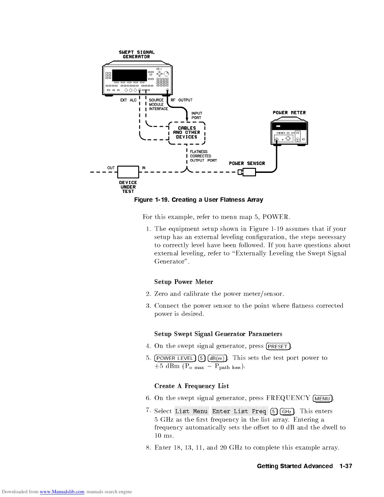
Figure 1-19. Creating a User Flatness Array
For this example, refer to menu map 5, POWER.
1. The equipment setup shown in Figure 1-19 assumes that if your
setup has an external leveling conguration, the steps necessary
to correctly level have b een followed. If you have questions ab out
external leveling, refer to \Externally Leveling the Swept Signal
Generator".
Setup Power Meter
2. Zero and calibrate the p ower meter/sensor.
3. Connect the power sensor to the p oint where atness corrected
power is desired.
Setup Swept Signal Generator Parameters
4. On the swept signal generator, press
4
PRESET
5
.
5.
4
POWER LEVEL
54
5
54
dB(m)
5
. This sets the test p ort p o
wer to
+5 dBm (P
o max
0
P
path loss
).
Create A Frequency List
6. On the swept signal generator, press FREQUENCY
4
MENU
5
.
7.
Select
NNNNNNNNNNNNNNNNNNNNNNNNNNNNN
List Menu
NNNNNNNNNNNNNNNNNNNNNNNNNNNNNNNNNNNNNNNNNNNNNNN
Enter List Freq
4
5
54
GHz
5
. This enters
5 GHz as the rst frequency in the list array
.Entering a
frequency automatically sets the oset to 0 dB and the dw
ell to
10 ms.
8. Enter 18, 13, 11, and 20 GHz to complete this example array
.
Getting Started Advanced 1-37