Getting Started 1
Agilent InfiniiVision 2000 X-Series Oscilloscopes User's Guide 39
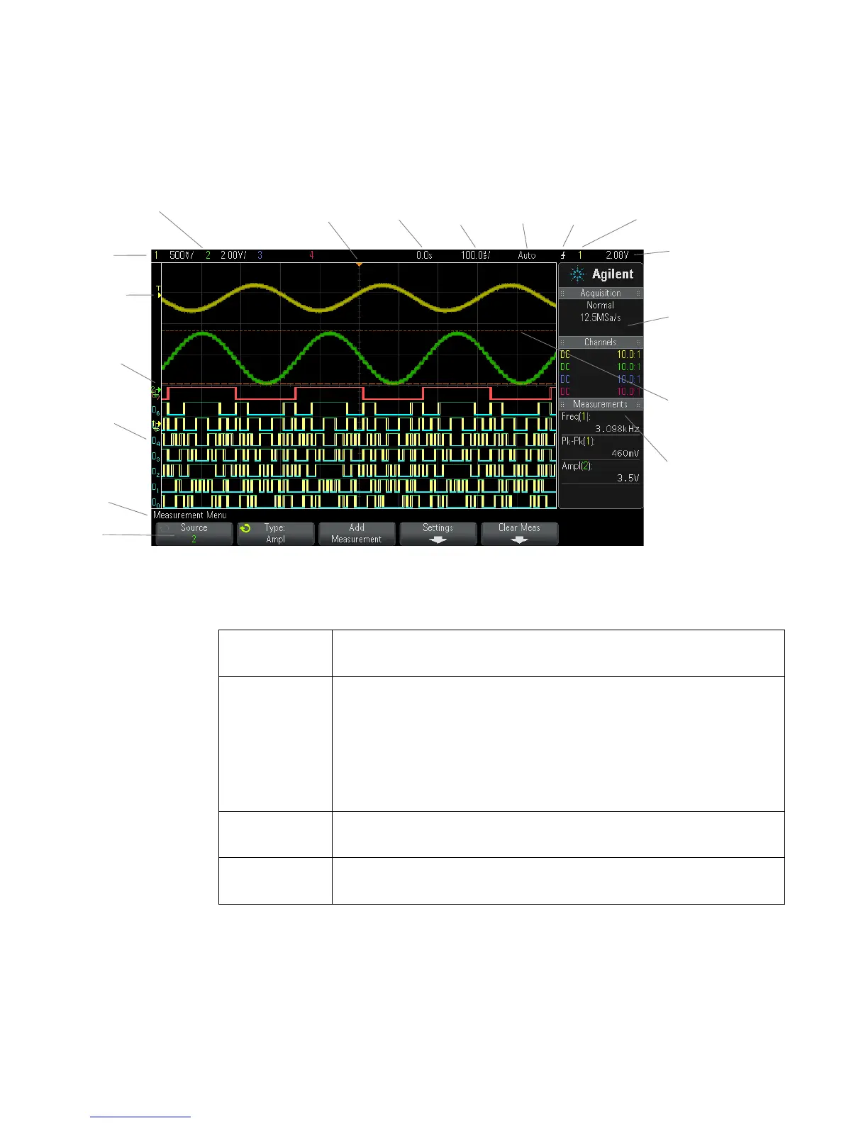
Figure 1 Interpreting the oscilloscope display
Status line The top line of the display contains vertical, horizontal, and trigger setup
information.
Display area The display area contains the waveform acquisitions, channel identifiers, and
analog trigger, and ground level indicators. Each analog channel's information
appears in a different color.
Signal detail is displayed using 256 levels of intensity. For more information
about viewing signal detail see “To adjust waveform intensity" on page 101.
For more information about display modes see Chapter 7, “Display Settings,”
starting on page 101.
Information area The information area normally contains acquisition, analog channel,
automatic measurement, and cursor results.
Menu line This line normally contains menu name or other information associated with
the selected menu.
Analog channel
sensitivity
Status line
Analog
channels
and ground
levels
Trigger level
Digital channels
Softkeys
Menu line
Trigger point,
time reference
Delay
time
Time/
div
Run/Stop
status
Trigger
type
Trigger
source
Measurements
Trigger level or
digital threshold
Information area
Cursors defining
measurement
 Loading...


