Getting Started 1
Agilent InfiniiVision 2000 X-Series Oscilloscopes User's Guide 37
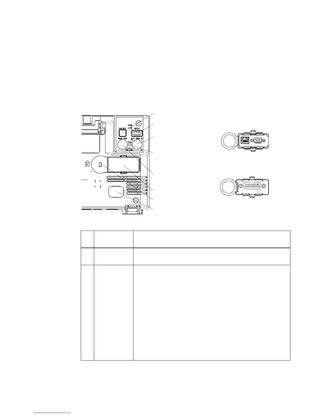
Learn the Rear Panel Connectors
For the following figure, refer to the numbered descriptions in the table
that follows.
1. Power cord
connector
Attach the power cord here.
2. Kensington
lock hole
This is where you can attach a Kensington lock for securing the
instrument.
3. Module slot No modules are included with the oscilloscope.
A DSOXLAN LAN/VGA module may be ordered and installed separately.
• LAN port — lets you communicate with the oscilloscope and use the
Remote Front Panel feature using the LAN port. See Chapter 20,
“Web Interface,” starting on page 257 and “Accessing the Web
Interface" on page 258.
• VGA video output — lets you connect an external monitor or projector
to provide a larger display or to provide a display at a viewing position
away from the oscilloscope.
The oscilloscope's built-in display remains on even when an external
display is connected. The video output connector is always active.
For optimal video quality and performance, we recommend you use a
shielded video cable with ferrite cores.
Also, a DSOXGPIB GPIB module may be ordered and installed separately.
a
a
:DWWV0$;
9+]
9+]
:$51,1*0$,17$,1
*5281'72 $92,'
(/(&75,&6+2&.
8. USB Device port
3. LAN/VGA
option module
3. GPIB
option module
7. USB Host port
1. Power cord connector
2. Kensington lock hole
4. TRIG OUT
connector
5. Calibration
protect
button
6. EXT TRIG IN
connector
3. Module slot
 Loading...


