Rockwell Automation Publication 1756-UM535D-EN-P - November 2012 277
Appendix F
Enhanced Redundancy System Checklists
Chassis Configuration Checklist
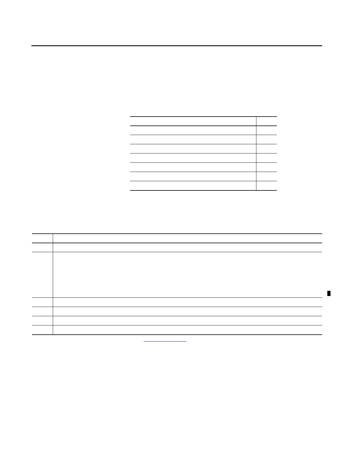
Topic Page
Chassis Configuration Checklist 277
Remote I/O Checklist 278
Redundancy Module Checklist 278
ControlLogix Controller Checklist 279
ControlNet Checklist 279
EtherNet/IP Module Checklist 280
Project and Programming Checklist 281
Requirement
Chassis used for the redundant pair are the same size, for example, both are 1756-A7, 7-slot chassis.
Only these modules are used in the redundant chassis:
• ControlLogix controllers, catalog numbers 1756-L61, 1756-L62, 1756-L63, 1756-L63XT,1756-L64, 1756-L65, 1756-L71, 1756-L72, 1756-L73, 1756-L73XT, 1756-L74,
1756-L75
• ControlNet communication modules, catalog numbers 1756-CN2/B, 1756-CN2R/B, 1756-CN2RXT
• EtherNet/IP communication modules, catalog numbers 1756-EN2T,1756-EN2TXT, 1756-EN2TR, 1756-EN2F
• Redundancy modules, catalog numbers 1756-RM, 1756-RMXT, 1756-RM2/A, 1756-RM2XT
Each chassis of the pair is comprised of identical modules that are of identical redundancy firmware revisions, series, and memory sizes.
(1)
Partner modules are placed in same slots of both chassis of the redundant pair (for example, the 1756-L63 is placed in slot 0 of both chassis).
I/O modules are not placed in the redundant chassis.
Seven or fewer communication modules of any type or combination are used in each redundant chassis.
(1) There are some exceptions to this requirement. For more information, see Redundant Chassis on page 28.
 Loading...

