66 Rockwell Automation Publication 1756-UM535D-EN-P - November 2012
Chapter 3 Install the Enhanced Redundancy System
Connect the Fiber-optic Communication Cable to Single Channels
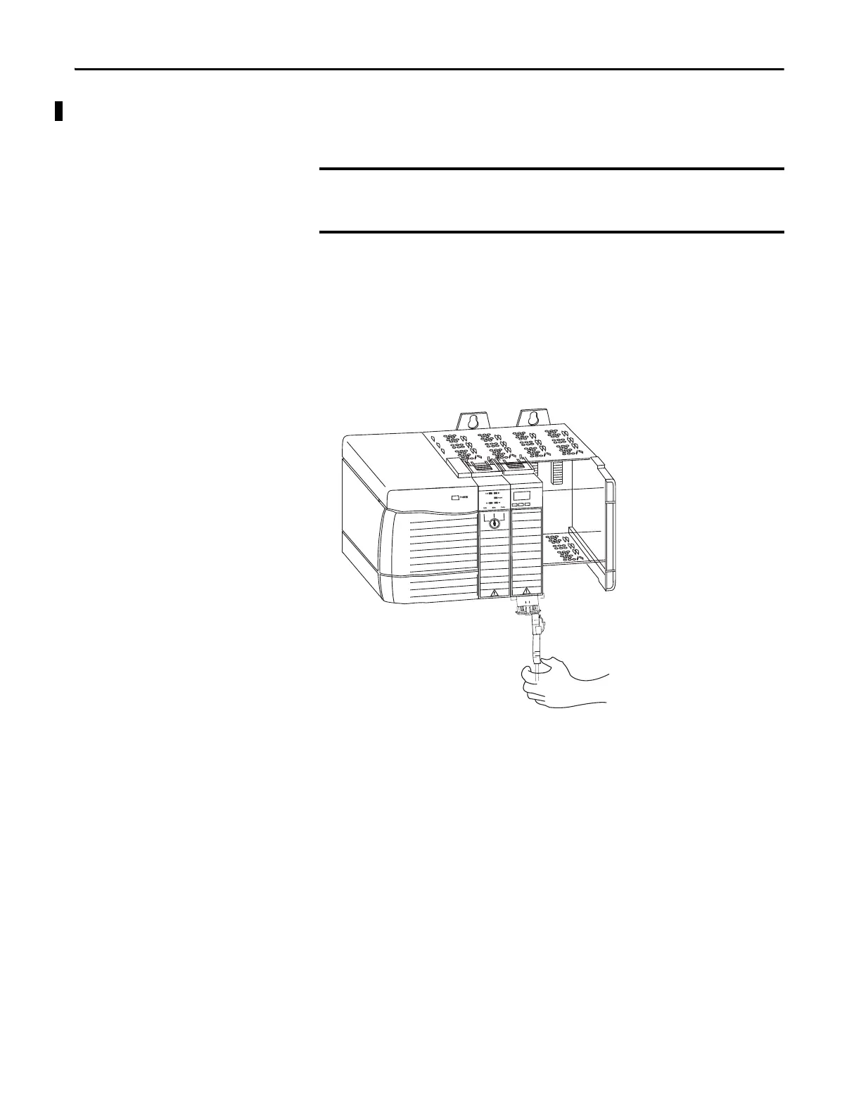
Follow this procedure to install the communication cable.
1. Remove the black protective plug on the first redundancy module in the
redundant chassis pair.
2. Remove the protective caps from the cable.
3. Plug the cable connector into the first redundancy module.
4. Plug the remaining cable-connector end to the second redundancy
module.
The redundancy module communication cable contains optical fibers. Avoid
making sharp bends in the cable. Install the cable in a location where it will
not be cut, run over, abraded, or otherwise damaged.
Logix5563
Redundancy Module
 Loading...

