Rockwell Automation Publication 1756-UM535D-EN-P - November 2012 67
Install the Enhanced Redundancy System Chapter 3
Fiber-optic Cable
If you choose to make your own fiber-optic cables, consider the following:
• Fiber-optic Communication Cable Specifications
• Determine Optical Power Budget
You can determine the maximum optical-power budget in decibels (dB)
for a fiber-optic link by computing the difference between the minimum
transmitter-output optical power (dBm avg) and the lowest receiver
sensitivity (dBm avg).
The optical-power budget provides the necessary optical-signal range to
establish a working fiber-optic link. You must account for the cable lengths
and the corresponding link penalties. All penalties that affect the link
performance must be accounted for within the link optical power budget.
Step 4: Update Redundant
Chassis Firmware
Use ControlFLASH software to upgrade the firmware of each module in
each chassis.
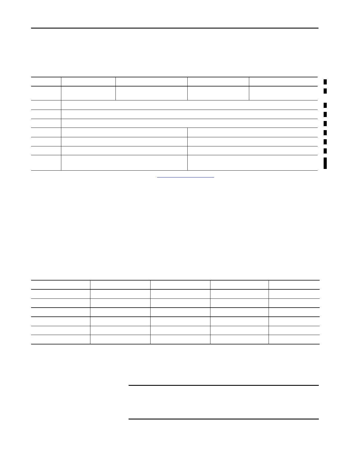
Attribute 1756-RM2/A 1756-RM2XT 1756-RM/A or 1756-RM/B 1756-RMXT
Temperature,
operating
0…60 °C (32…140 °F) -25…70 °C (-13…158 °F) 0…60 °C (32…140 °F) -25…70 °C (-13…158 °F)
Connector type LC-type (fiber-optic)
Cable type 8.5/125 micron single-mode fiber-optic cable
Channels 1 (transmit and receive fiber)
Length, max 10 km (10,000 m, 10936.13 yd 4 km (4000 m, 4,374.45 yd)
(1)
Transmission 1000 Mbps Less than or equal to 100 Mbps
Wavelength 1310 nm 1300 nm
SFP transceiver Transceiver Rockwell PN-91972
Connector/cable: LC duplex connector, 1000BASE-LX-compliant
——
(1) Longer distances are supported based on the systems’ optical power budget. See the Optical Power Budget Ranges on page 67.
Table 12 - Optical Power Budget Ranges
Transmitter Min Typical Max Unit
Output optical power -15 — -8 dBm
Wavelength 1261 — 1360 nm
Receiver Min Typical Max Unit
Receiver sensitivity — -38 -3 dBm avg
Receiver overload -8 — — dbm avg
Input operating wavelength 1261 — 1580 nm
Apply power ONLY to the chassis containing modules on which you are
upgrading firmware.
Upgrade firmware on only one module at a time.
 Loading...

