Rockwell Automation Publication 1756-UM535D-EN-P - November 2012 61
Install the Enhanced Redundancy System Chapter 3
A redundant system is comprised of two ControlLogix redundancy modules
working together that supervise the operating states and state transitions that
establish the basic framework for redundancy operations. The redundant pairs
provide a bridge between chassis pairs that let other modules exchange control
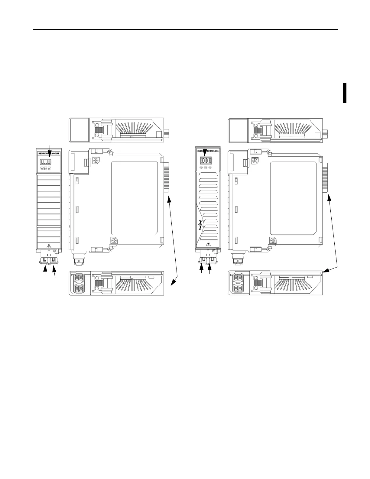
data and synchronize their operations. This illustration identifies the external
features of the module.
Figure 12 - 1756-RM2/A or 1756-RM2XT Modules
32269-M
46057
1756-RM2/A Module
1756-RM2XT Module
Backplane
Connector
Front View
Top View
Bottom View
Side View
Status Indicators
Front View
Top View
Bottom View
Side View
Status Indicators
Backplane
Connector
CH2 CH1
CH2 CH1
NOTE: SFP transceivers are pre-installed in the redundant fiber ports
 Loading...

