136 Rockwell Automation Publication 1441-UM001B-EN-P - September 2012
Chapter 5 Collecting and Reviewing Data
Bias Check
The Bias function checks the bias of the transducer before taking the
measurement. There are two options for the Bias Check parameter, Automatic
and Manual.
When you are in the Route Hierarchy, you can check the bias voltage for ICP
measurements manually by pressing 0 (Shift)+2 (B) to.
This turns on the ICP supply (if it wasn't already) and measures the DC bias
voltage for each channel used by this measurement.
Channel X for single channel points. Typically X and Y is for two-channel points,
and X, Y, and Z for Triax points.
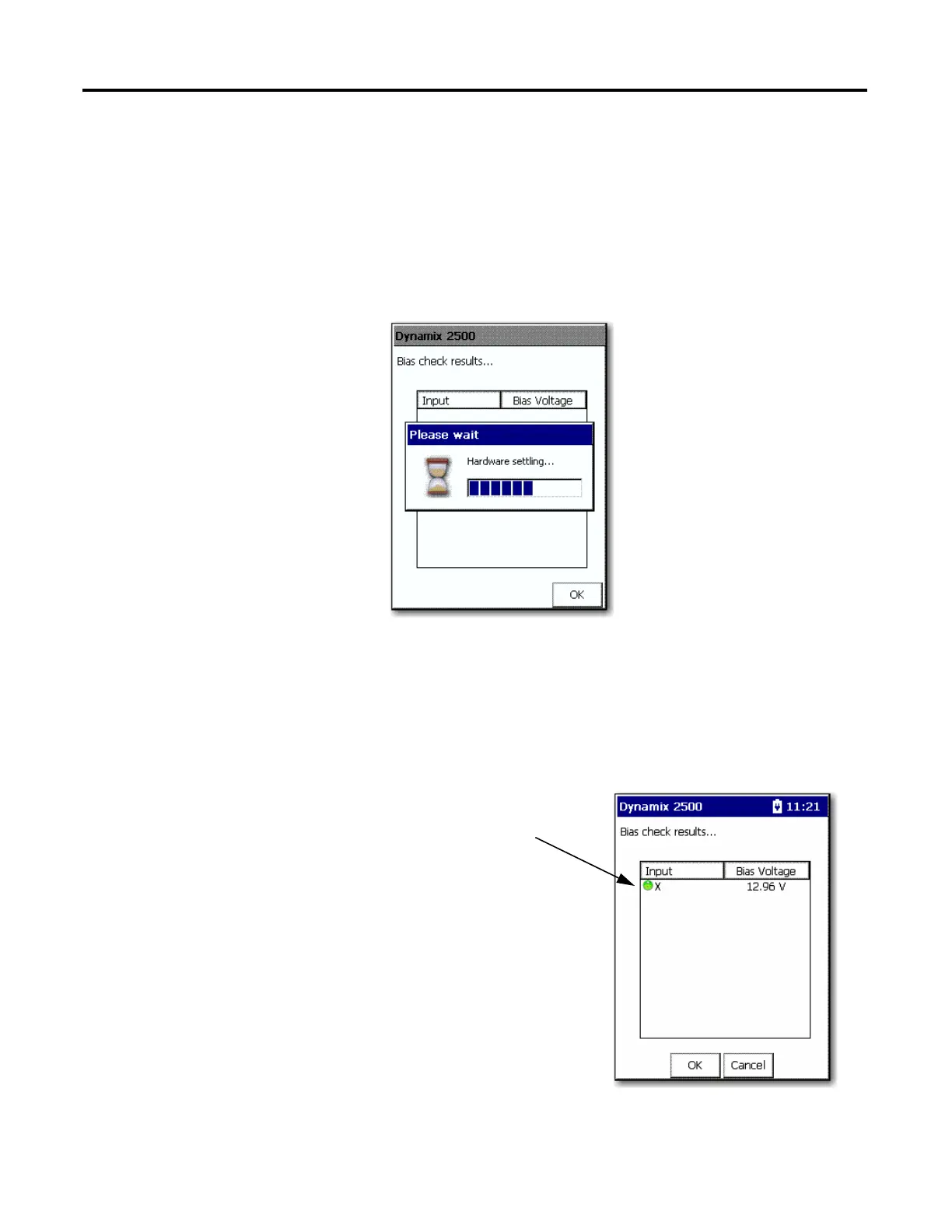
The Bias check screen shows the voltages for each channel.
The Bias check results screen
displays a red or green input
indicator.
Green appears when the bias
voltage is between 2V and 18V,
which is regarded as normal.
Red appears if it is outside this
range.
This can be useful when
troubleshooting a cable or
accelerometer.
 Loading...