Rockwell Automation Publication 1441-UM001B-EN-P - September 2012 19
The Dynamix 2500 Data Collector Chapter 1
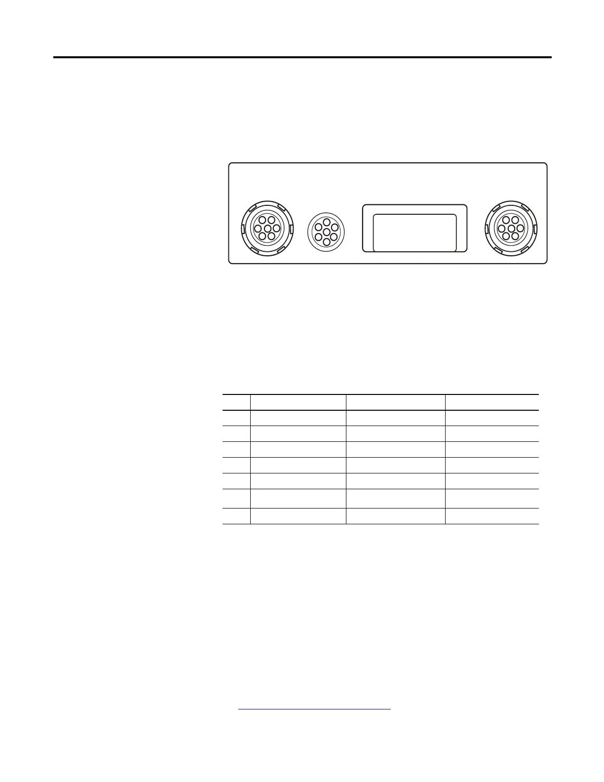
External Connections
The external hardware connections for communication and data collection are
located on the top panel of the Dynamix 2500 data collector.
Figure 2 - External Hardware Connections
Connector A and Connector B Inputs
The data collector has two signal inputs (LEMO connectors), connector A and
B. Headphone access is supported on Connectors A and B.
The measurement Input signal range is ±25 V maximum. Input over voltage
protection is AC ± 50 V peak, DC ± 50 V. The inputs are protected ±50 V AC
or DC sustained against high-voltage transients, but trigger range over-voltage
input levels must be avoided.
Voltage can be DC or AC coupled, while the third option, Accel (ICP) 24 V DC
@ 2.4mA, is available for direct connection of integrated circuit piezoelectric
transducers. These settings are specified in the Emonitor software.
See Setting Up Measurements on page 65
for more information.
A
POWER/USB/
TRIGGER
LASER
B
32144-M
1
5
6
7
4
3
2
1
5
6
7
4
3
2
1
2
3
4
5
6
7
Table 5 - Dynamix 2500 Data Collector Pin Assignments
Pin Connector A Connector B POWER/USB/TRIG
1 Audio Output Audio Output USBV
2 Channel X Channel Y USB+
3 Channel Z N/C USB-
4 Strobe Out Strobe Out DIGITAL GND
5 ANALOG GND ANALOG GND EXT-DC-IN
6 Channel Y N/C
± 25 V EXT-TRIG-IN
7 Channel R Channel Z +5V DC TACHO SUPPLY
In some circumstances you may find a reference to channel numbers
instead of X, Y, Z or R. Channel numbers can be cross referenced to
X= Ch(1), Y = Ch(2), Z= Ch(3), R = Ch(4).
 Loading...