76 Rockwell Automation Publication 1441-UM001B-EN-P - September 2012
Chapter 3 Setting Up Measurements
The table for the transducer specification in the STD (Hz) 2000 collection
specification would look like this.
Measurement Input Types
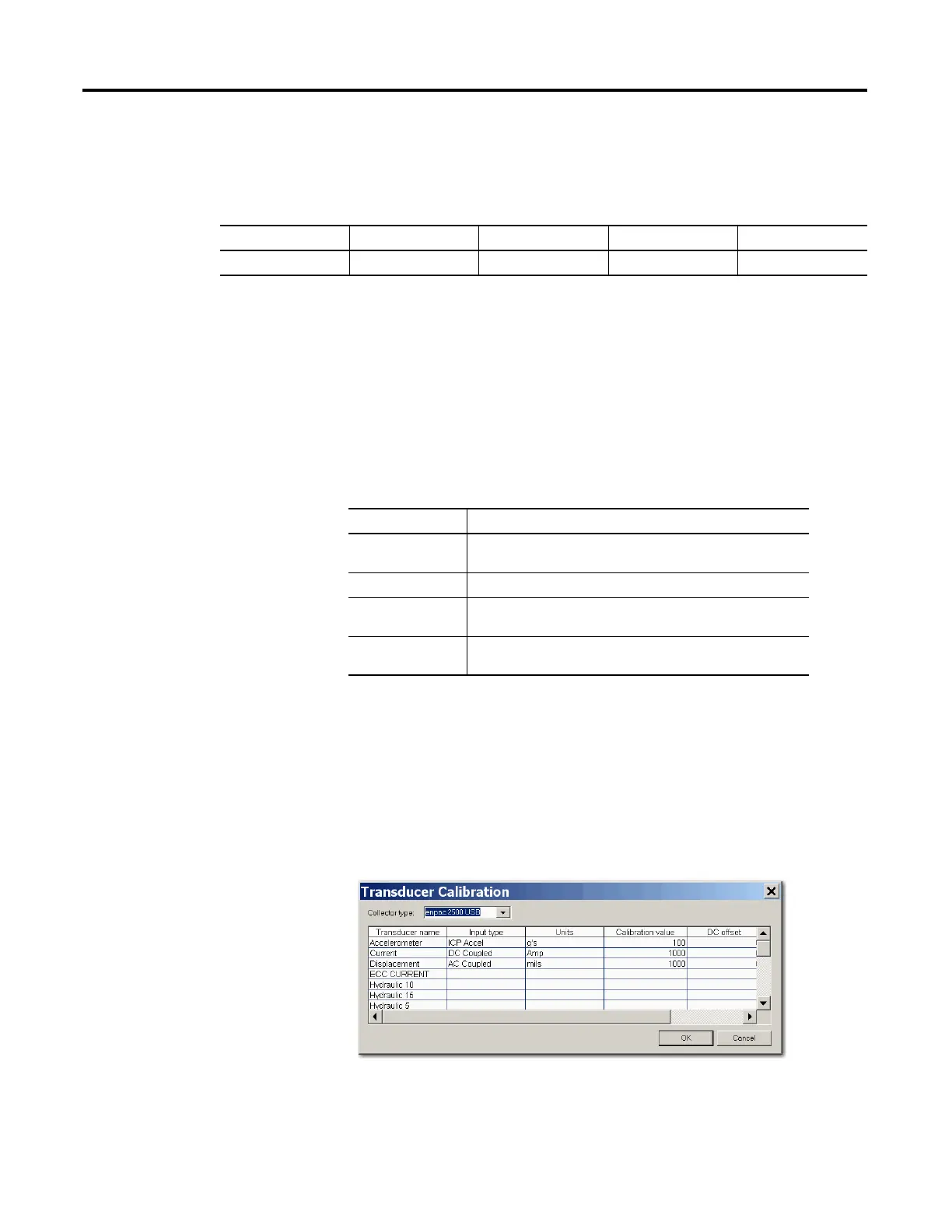
The input type is part of the transducer specification (Setup > Calibration). The
transducer is part of the collection specification (Setup > Collection). You select
the collection specification when you set up the measurement definition.
The Emonitor software and the Dynamix 2500 data collector support the
following input types.
Follow these to specify an input type.
1. Select Setup > Calibration.
2. Choose the correct Dynamix 2500 data collector from the Collector list.
3. Assign Input types, Calibration, and appropriate Units to the transducer.
Figure 14 - Transducer Calibration dialog box
Table 20 - Transducer specification in STD (Hz) 2000 collection specification
Name Base Unit Input Type Units DC Offset
Accelerometer Acceleration ICP Accel g’s 0
Input Type Description
ICP Accel Use for ICP accelerometers requiring current from a power
supply.
AC Coupled Use for AC voltage measurements and non-ICP accelerometers.
DC Coupled Use for DC voltage measurements. This includes numeric
(process) measurements taken from a DC voltage output.
Manual Entry Use for numeric (process) measurements where you enter the
value for the measurement with the data collector keyboard.
 Loading...