88 Rockwell Automation Publication 1441-UM001B-EN-P - September 2012
Chapter 3 Setting Up Measurements
3. Finish setting up the dynamic proximity probe measurement by setting
Data Type to Magnitude and Units to mils or um.
You can use a Filter if desired.
Follow these steps to setup a Static (DC) component or gap.
1. Set up a displacement transducer in the Transducer Calibration dialog box
with Input type set to DC Coupled and Units set to mils or um.
Make sure you enter the Calibration value that converts the voltage to a
displacement. If you are using the DC Input Module to remove the AC
component and attenuate the signal be a factor of 2.5, then you must
divide your transducer’s calibration by 2.5.
2. Set up a Collection Specification with Transducer set to the DC
displacement and Signal detection set to RMS.
3. Finish setting up the dynamic proximity probe measurement by setting
Data Type to Magnitude and Units to mils or um.
You must set the Filter to None because any type of high pass filtering
removes the DC component.
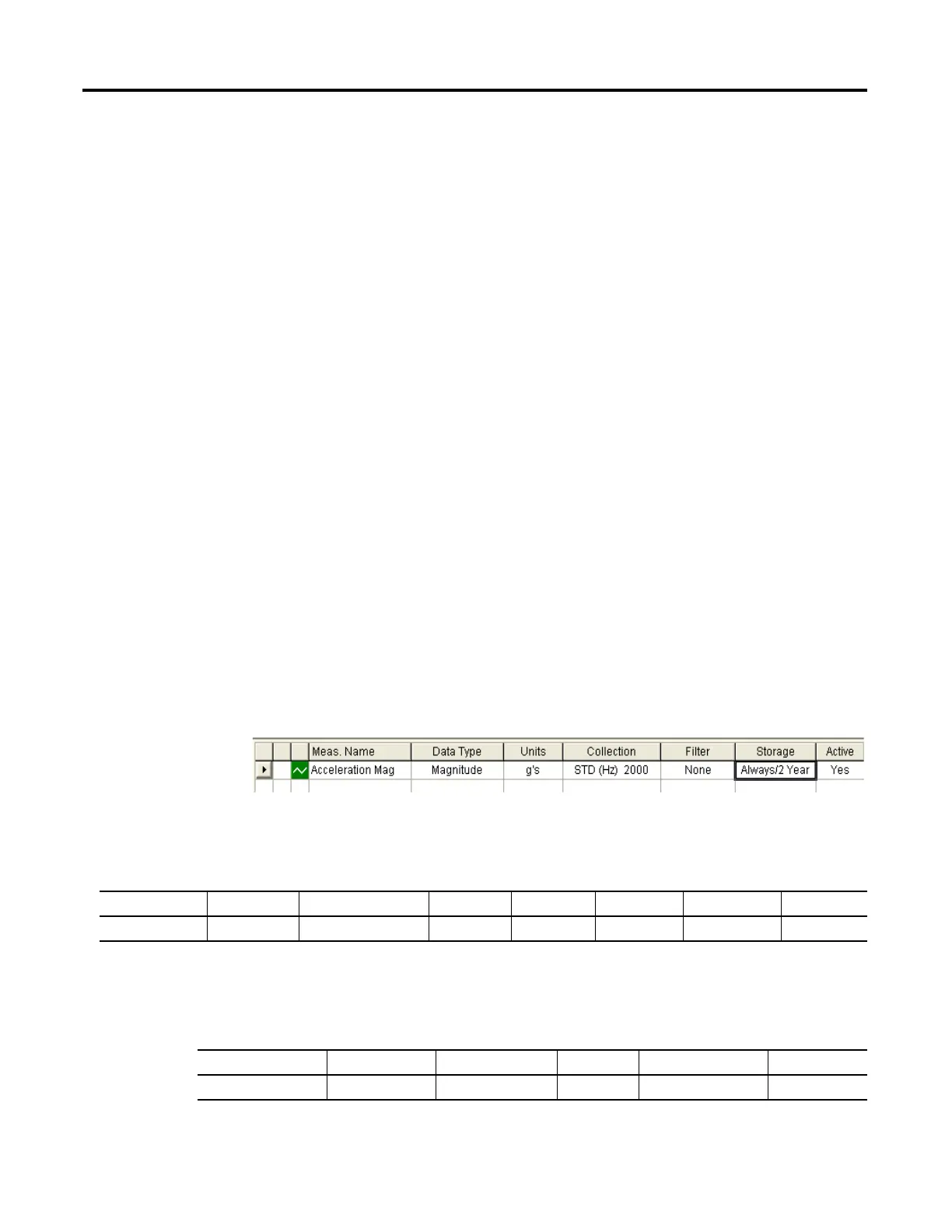
Typical Magnitude Measurement Definitions
This figure shows the setup for a typical magnitude measurement definition
Figure 15 - Magnitude measurement definition
The following table shows the STD (Hz) 2000 collection specification.
The following table shows the transducer specification in the STD (Hz) 2000
collection specification.
Table 24 - Collection specification for magnitude measurement definition
Transducer Window Signal Detection Fmax Lines Phase Order Norm? Averages
Accelerometer Hanning Peak 2 kHz 400 No No 4 linear
Table 25 - Transducer specification in STD (Hz) 2000 collection specification
Name Base Unit Input Type Units Calibration Value DC Offset
Accelerometer acceleration ICP Accel g’s 100 0
 Loading...