94 Rockwell Automation Publication 1441-UM001B-EN-P - September 2012
Chapter 3 Setting Up Measurements
6. Connect the speed sensor to the trigger connector on the Dynamix 2500
data collector when collecting data.
Magnitude Alarms in the Dynamic 2500 Data Collector
You can use magnitude alarms with numeric measurements:
• The Dynamix 2500 data collector supports above, below, in window, and
out of window magnitude alarms with numeric measurements.
• You must set Trigger to Yes for any alarms you want to appear in the
Dynamix 2500 data collector during data collection.
For more on how the Emonitor software combines alarms before sending
them to the Dynamix 2500 data collector, see Alarms and the Data
Collector on page 104.
Typical Numeric Measurement Definitions
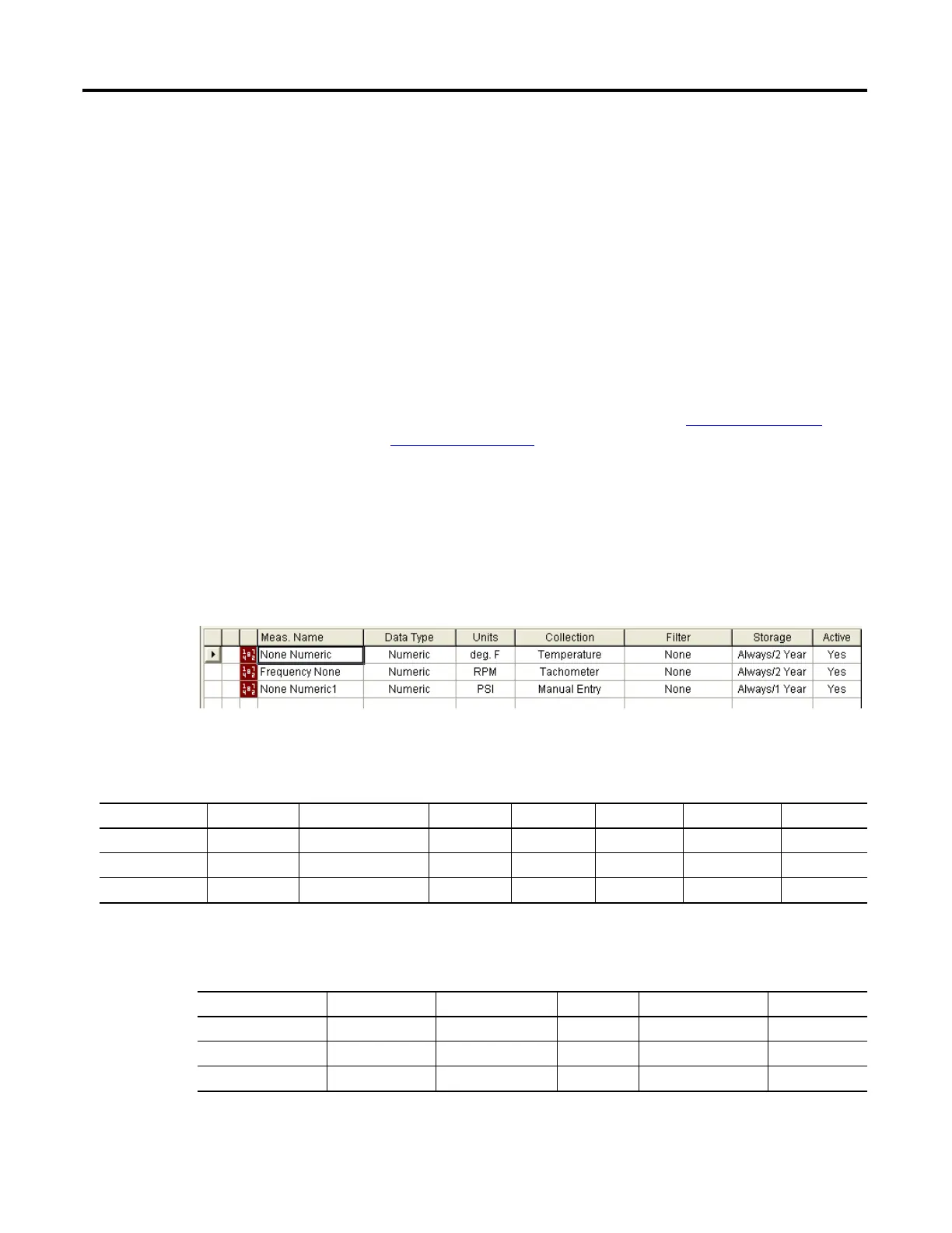
This figure shows the setup for typical numeric measurement definitions. The
first two measurements are numeric (DC) voltage measurements, and the third is
a numeric manual entry measurement.
Figure 18 - Numeric measurement definitions
The collection specifications appear in the table below. N/A means not applied.
This table shows the transducer specifications in the collection specifications
.
Table 30 - Collection specifications for numeric measurement definitions
Transducer Window Signal Detection Fmax Lines Phase Order Norm? Averages
Temperature N/A RMS N/A N/A No No N/A
Tachometer N/A None N/A N/A No No N/A
Manual Entry N/A None N/A N/A No No N/A
Table 31 - Transducer specifications in numeric collection specifications
Name Base Unit Input Type Units Calibration Value
(1)
DC Offset
Temperature Temperature DC Coupled deg. F See note below. 0
Tachometer Frequency DC Coupled rpm See note below. 0
Manual Entry None Manual Entry None See note below. 0
(1) Make sure you enter the Calibration value that converts the voltage to a known unit such as speed.
 Loading...