Publication 1763-UM001E-EN-P - June 2015
Using the LCD 101
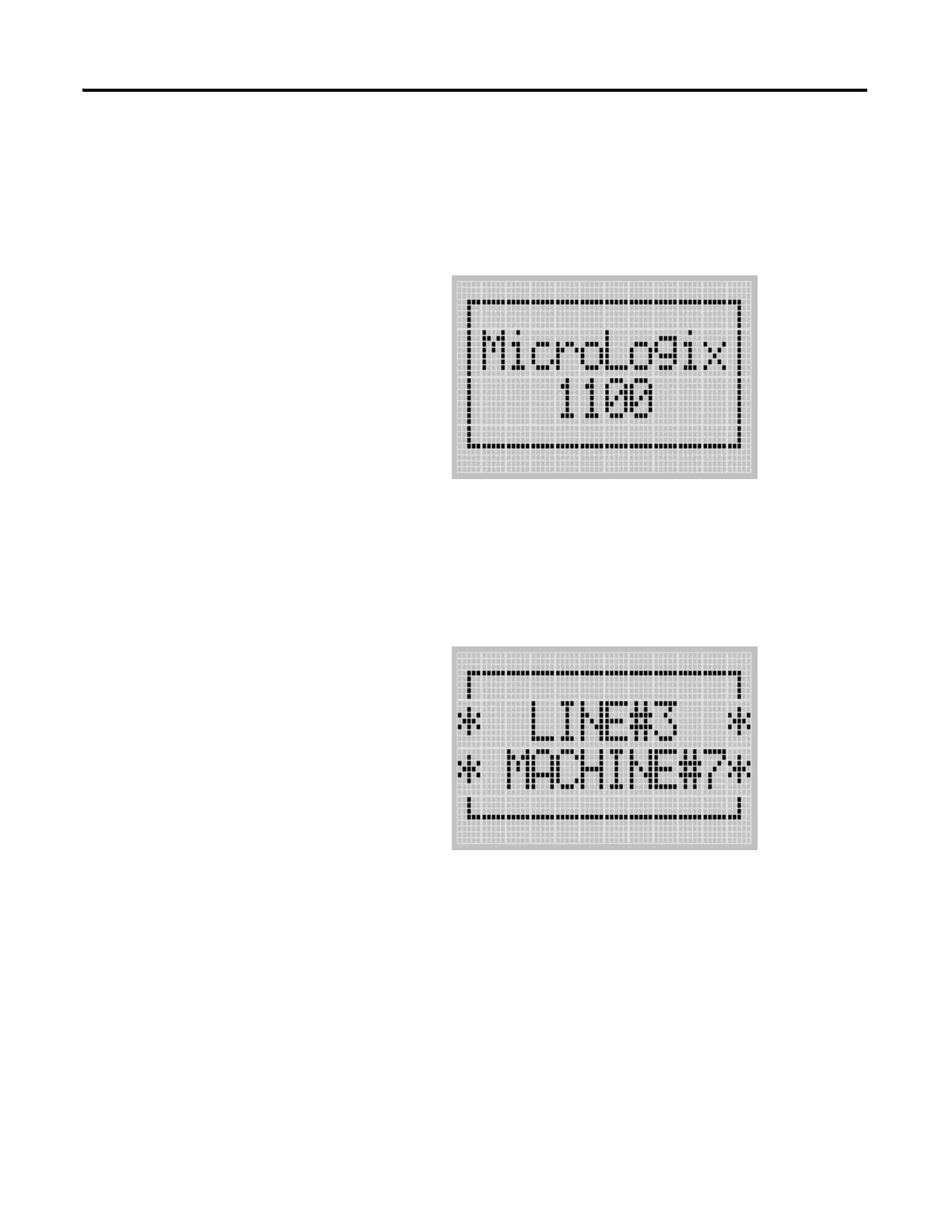
Startup Screen
The Startup screen is displayed whenever the controller is powered up.
LCD Default Startup Screen
You can customize this Startup screen in your application program by defining
a string data file that contains the string to display on the Startup screen and
specifying the CBS element of the LCD Function File to the address of this
string file.
The screen shown below is an example of a customized Startup screen.
For more information on how to create and use a customized Startup screen,
refer to the LCD Function File described in the MicroLogix 1100
Programmable Controllers Instruction Set Reference Manual, publication
1763-RM001.
After the default Startup screen or your customized Startup screen is displayed
for 3 seconds, either the default screen (the I/O Status screen) is displayed by
default, or a user defined screen is displayed if your application uses a custom
default screen.

 Loading...


