Publication 1763-UM001E-EN-P - June 2015
Using the LCD 137
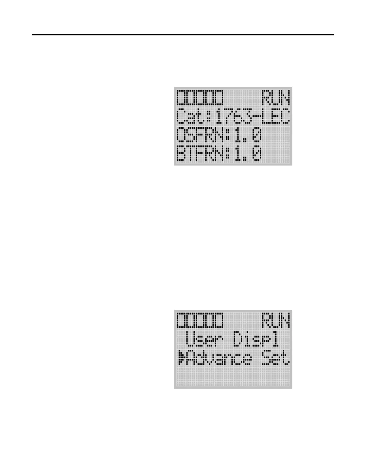
4. The System Information screen is displayed.
You can identify the catalog number, operating system firmware revision
number, and boot firmware revision number of your controller.
5. Press the ESC key to return to the Advanced Settings Menu screen, as
shown in step 3.
Viewing Fault Code
The Fault Code screen of the LCD displays the fault code when a fault occurs.
When a fault occurs, the Fault Code screen is not displayed automatically. Only
the FAULT LED on the controller flashes in red light. Therefore, you need to
navigate into the Fault Code screen to identify the fault code on the LCD.
Follow these steps to view the fault code when a fault occurs.
1. On the Main Menu screen, select Advance Set by using the Up and
Down keys on the LCD keypad, as shown below. If the menu items
shown in the figure below are not displayed on the Main Menu screen,
you need to scroll down the screen by pressing the Down key.

 Loading...


