Publication 1763-UM001E-EN-P - June 2015
140 Using Real-Time Clock and Memory Modules
Writing Data to the Real-Time Clock
When valid data is sent to the real-time clock from the programming device or
another controller, the new values take effect immediately.
The real-time clock does not allow you to load or store invalid date or time
data.
RTC Battery Operation
The real-time clock uses the same replaceable battery that the controller uses.
The RTC Function File features a battery low indicator bit (RTC:0/BL), which
shows the status of the replacement battery. When the battery is low, the
indicator bit is set (1). This means that the battery wire connector could be
disconnected or if the battery is connected, the battery may be ready to fail in
the next two weeks. In the latter case, the replacement battery needs to be
replaced with a new one. When the battery low indicator bit is clear (0), the
battery level is acceptable.
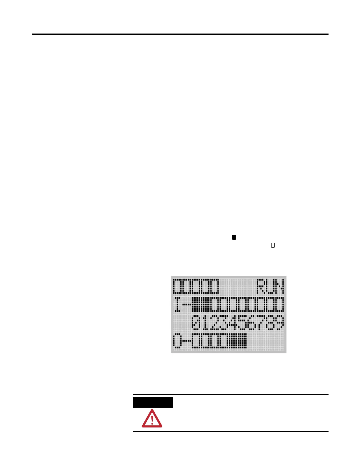
The Battery Low (BAT.LO) indicator on the LCD display of the controller
also shows the status of the replaceable battery. When the battery is low, the
indicator is displayed as solid rectangle ( ). When the battery level is
acceptable, the indicator is displayed as emty rectangle ( ), as shown below.
If the RTC battery is low and the controller is powered, the RTC operates
normally. If the controller power is removed and the RTC battery is low, RTC
data is lost.
Operating with a low battery indication for more
than 2 weeks (8 hours without a battery) may result
in invalid RTC data unless power is on continuously.
COMM0
CO
MM1
D
COM
M
BAT.L
O
U
-MSG

 Loading...


