Publication 1763-UM001E-EN-P - June 2015
Communication Connections 73
indicator on the LCD display operates to show when the controller is in the
default communications mode (settings shown on 72).
Changing Communication Configuration
Follow the procedure below to change from the user-defined communication
configuration to the default communications mode and back. In this example,
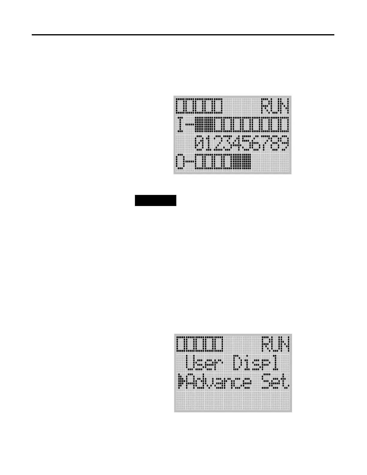
we will start from the Main Menu screen of the LCD display, as shown below.
If necessary, press ESC repeatedly until you return to the Main Menu screen.
1. On the Main Menu screen, select Advance Set by using the Up and
Down keys on the LCD keypad, as shown below. If the menu items
shown in the figure below are not displayed on the Main Menu screen,
you need to scroll down the screen by pressing the Down key.
The Communication Toggle Functionality only
affects the communication configuration of
Channel 0.
COM
M
0
COM
M
1
DCOMM
BAT. LO
U-MSG

 Loading...


