Publication 1763-UM001E-EN-P - June 2015
108 Using the LCD
Viewing I/O Status
Follow these steps to view the status of inputs and outputs on the LCD.
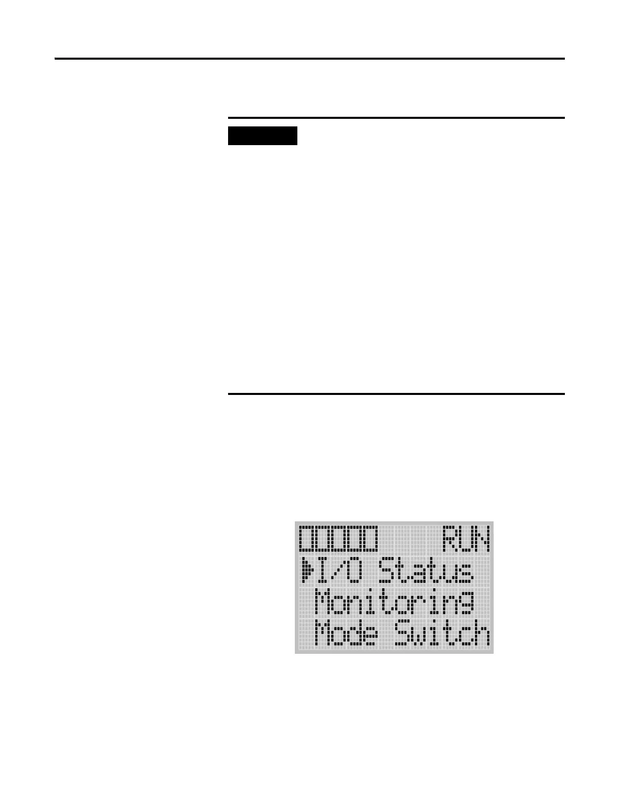
1. On the Main Menu screen, select I/O Status by using the Up and Down
keys on the LCD keypad, as shown below.
If a user defined LCD screen is used, the I/O S
sctatus sreen is displayed,
• When the user holds down the ESC key for more
than 3 seconds.
• When time out is enabled, i.e., the time out
period is set to a positive value, and the time out
period is passed. You can enable and disable
time out and set the time out period using the TO
element in the LCD Function File. For more
information, refer to the LCD Function File
described in the MicroLogix 1100 Programmable
Controllers Instruction Set Reference Manual,
publication 1763-RM001.
• If time out is disabled, i.e., the time out period is
set to zero (0), and a custom LCD screen is
displayed, it will be displayed continuously until
the user gives an input to change to other screen.
For more information, see Using a User Defined LCD
Screen on page 5-126.

 Loading...


