Publication 1763-UM001E-EN-P - June 2015
220 Connecting to Networks via Ethernet Interface
In order to receive messages from another device on Ethernet, an “incoming”
connection must be established. This incoming connection is made by the
sending processor and uses one incoming connection in the receiving
processor.
The MicroLogix 1100 supports a maximum of 32 connections, allowing a
maximum of 16 outgoing and a maximum of 16 incoming simultaneous
connections with up to 32 other devices or applications. The connections are
dedicated as follows:
Duplicate IP address
Detection
The MicroLogix 1100 Series B firmware support duplicate IP address
detection.
When you change the IP address or connect one of the MicroLogix to an
EtherNet/IP network, the MicroLogix 1100 controller checks to make sure
that the IP address assigned to this device does not match the address of any
other network device. The MicroLogix 1100 will check every 2 minutes for a
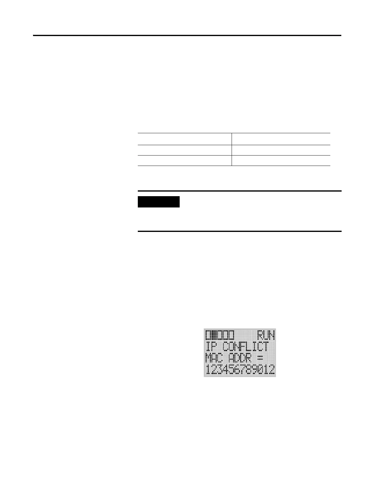
duplicate IP address on the network. If the MicroLogix 1100 determines that
there is a conflict (another device on the network with a matching IP address),
the following message gets posted on the LCD display.
To correct this conflict, use the instructions in this chapter to change the IP
address of the Ethernet/IP device. Then cycle power to the device or reset
the device (such as disconnecting the ethernet cable and reconnecting the
cable).
There is also the possibility that two Ethernet/IP device can detect a conflict
simultaneously. If this occurs, remove the device with the incorrect IP address
or correct its conflict. To get the second device out of conflict mode, cycle
power to the module or disconnect its ethernet cable and reconnect the cable.
Number of Connections
(1)
(1)
Connections established by an INTERCHANGE client, RSLinx client, and peers are all included when
counting the number of connections.
Dedicated to:
16 outgoing connections
16 incoming connections
For outgoing connections, no more that one
connection per destination node is established. If
multiple MSG instructions use the same destination
node, they share the same connection.

 Loading...


