Publication 1763-UM001E-EN-P - June 2015
38 Installing Your Controller
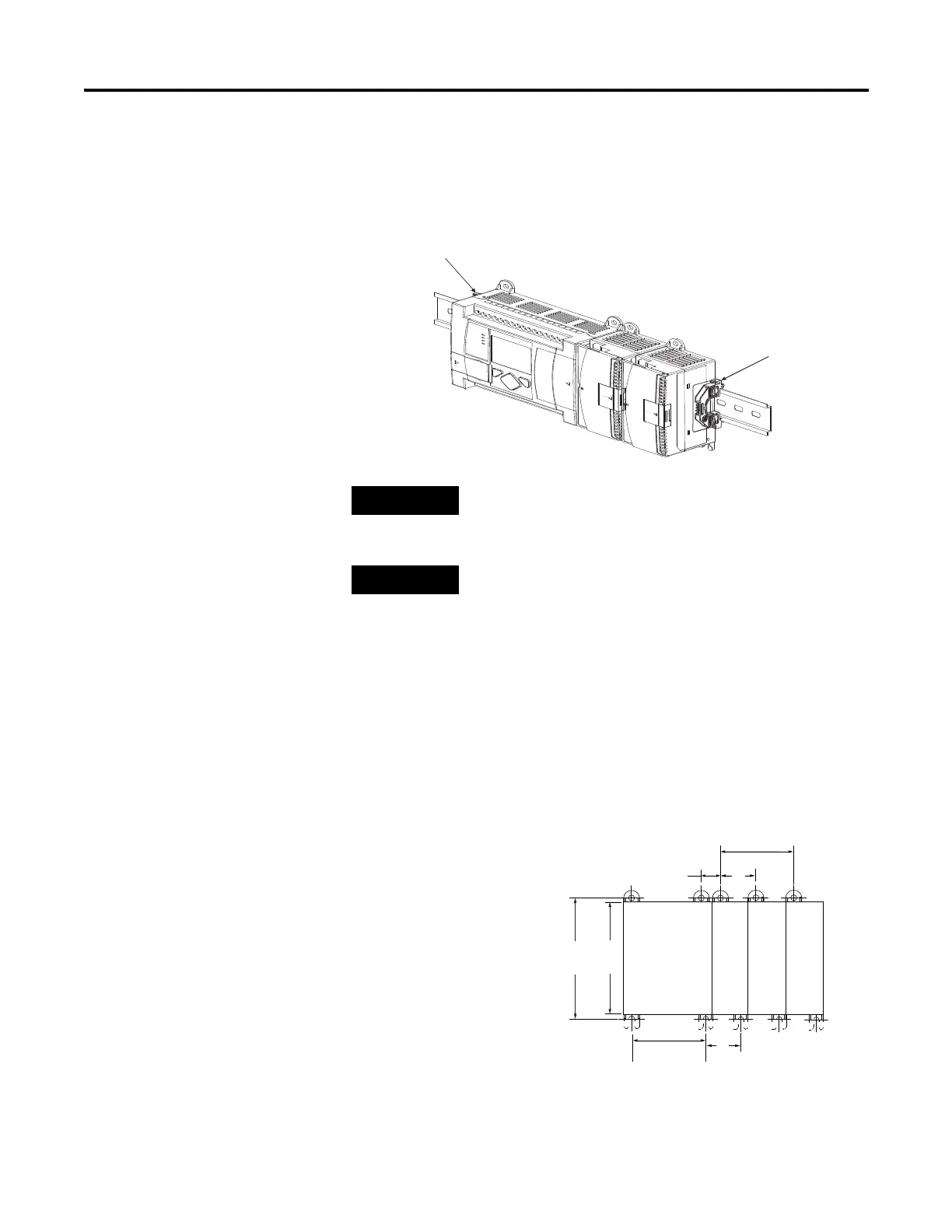
Use DIN rail end anchors (Allen-Bradley part number 1492-EA35 or
1492-EAH35) for vibration or shock environments. The following illustration
shows the location of the end anchors.
Panel Mounting
Use the dimensional template shown below to mount the module. The
preferred mounting method is to use two M4 or #8 panhead screws per
module. Mounting screws are required on every module.
1762 expansion I/O must be mounted horizontally as
illustrated.
For environments with greater vibration and shock
concerns, use the panel mounting method described below,
instead of DIN rail mounting.
90
(3.54)
100
(3.94)
40.4
(1.59)
A
40.4
(1.59)
14.5
(0.57)
MicroLogix
1100
1762 I/O
1762 I/O
1762 I/O
For more than 2 modules: (number of modules - 1) x 40 mm (1.59 in.)
NOTE: All dimensions are in mm (inches).
Hole spacing tolerance: ±0.4 mm (0.016 in.).
A = 95 mm (3.740 in.)
1763-L16AWA, 1763-L16BWA, 1763-L16BBB

 Loading...


