Publication 1763-UM001E-EN-P - June 2015
Chapter
1
Hardware Overview
Hardware Features
The Bulletin 1763, MicroLogix 1100 programmable controller contains a
power supply, input and output circuits, a processor, an isolated combination
RS-232/485 communication port, and an Ethernet port. Each controller
supports 18 I/O points (10 digital inputs, 2 analog inputs, and 6 discrete
outputs).
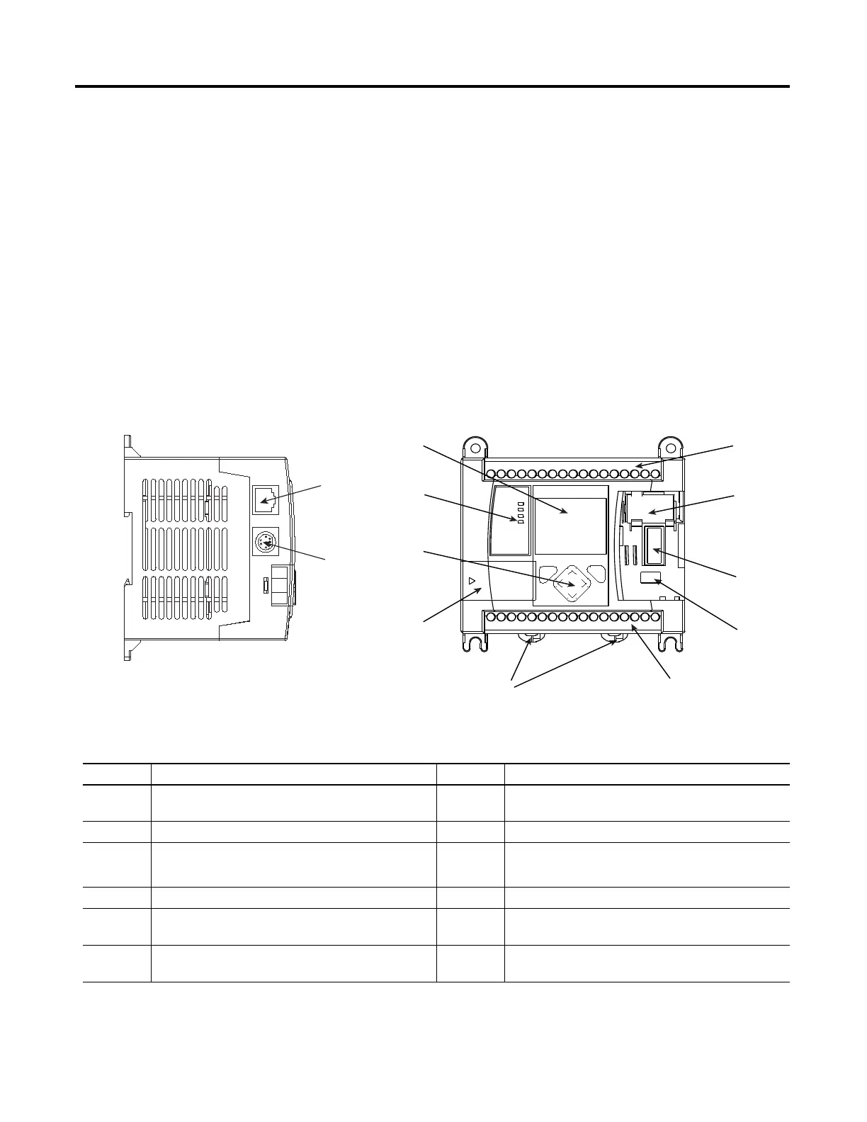
The hardware features of the controller are shown below.
Hardware Features
Feature Description Feature Description
1 Output Terminal Block 7 LCD Keypad
(ESC, OK, Up, Down, Left, Right)
2 Battery Connector 8 Status LED indicators
3 Bus Connector Interface to Expansion I/O 9
Memory Module Port Cover
(1)
-or-
Memory Module
(2)
4 Battery 10 DIN Rail Latches
5 Input Terminal Block 11 RS-232/485 Communication Port
(Channel 0, isolated)
6 LCD 12 Ethernet Port
(Channel 1)
(1)
Shipped with controller.
(2)
Optional equipment.

 Loading...


