Publication 1763-UM001E-EN-P - June 2015
Communication Connections 97
Connecting to Ethernet
You can connect directly a MicroLogix™ 1100 to an Ethernet network via the
Ethernet port (Channel 1). You do not need to use an Ethernet interface card,
such as the Ethernet Interface (ENI) and (ENIW), catalog number
1761-NET-ENI and 1761-NET-ENIW, to connect your MicroLogix 1100
controller to an Ethernet network. For additional information on connecting
to an Ethernet network, see Appendix F.
Ethernet Connections
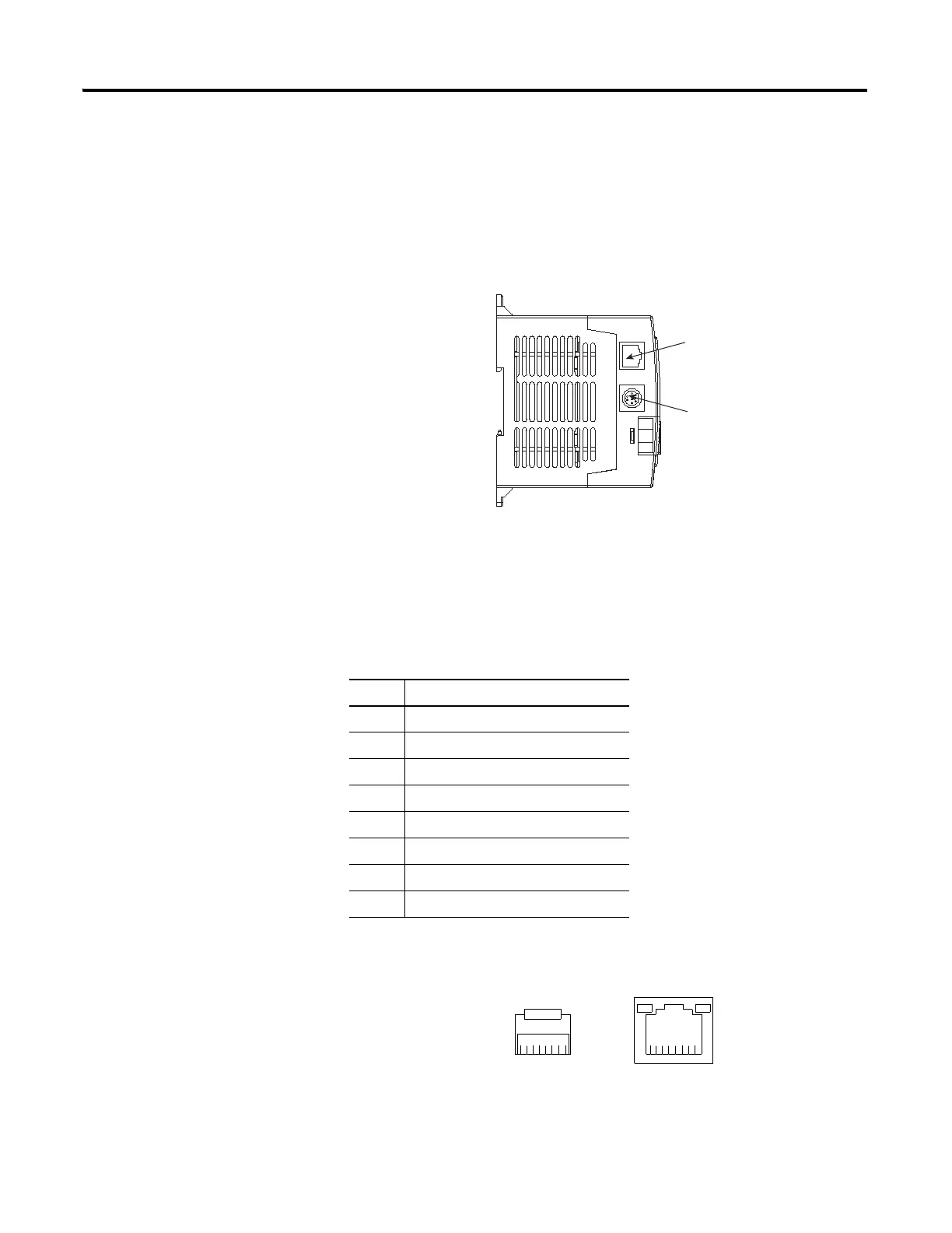
The Ethernet connector, Channel 1, is an RJ45, 10/100Base-T connector. The
pin-out for the connector is shown below.
Pin Pin Name
1Tx+
2Tx-
3Rx+
4 not used by 10/100Base-T
5 not used by 10/100Base-T
6Rx-
7 not used by 10/100Base-T
8 not used by 10/100Base-T
RS-232/485 Port (Channel
Ethernet Port (Channel 1)
8 7 6 5 4 3 2 11 2 3 4 5 6 7 8
End view of RJ 45 Plug Looking into a RJ45 Jack

 Loading...


