EasyManuals Logo

Allen-Bradley MicroLogix 1100 User Manual

Allen-Bradley MicroLogix 1100
256 pages
To Next Page IconTo Next Page
To Previous Page IconTo Previous Page
Page #15 background imageLoading...
Page #15 background image
Publication 1763-UM001E-EN-P - June 2015
Hardware Overview 13
1763-MM1 Memory Module
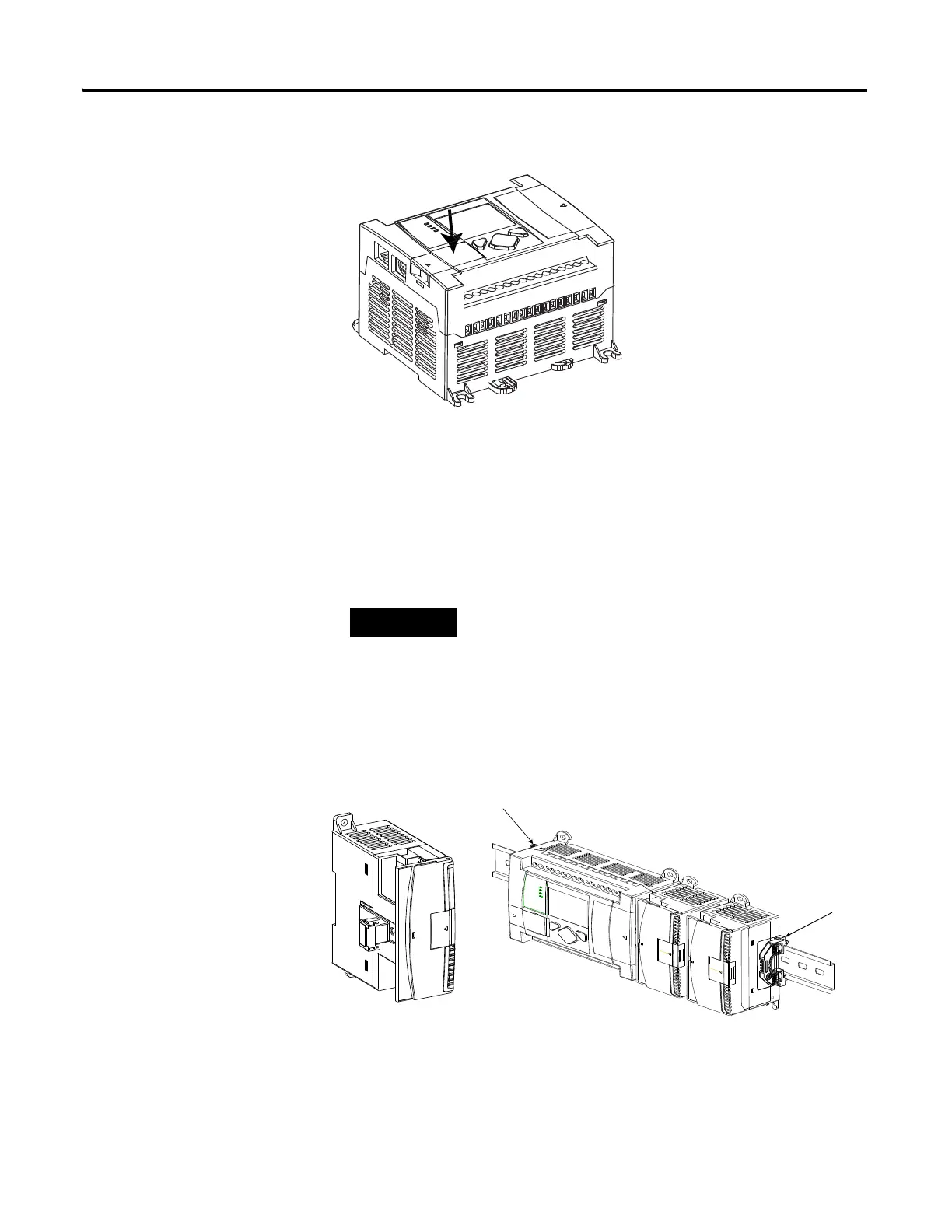
1762 Expansion I/O
1762 expansion I/O can be connected to the MicroLogix 1100 controller, as
shown below.
1762 Expansion I/O
TIP
A maximum of four I/O modules, in any combination, can
be connected to a controller. See Appendix G to determine
how much heat a certain combination generates.
1762 Expansion I/O 1762 Expansion I/O Connected to MicroLogix 1100 Controller

Table of Contents

Other manuals for Allen-Bradley MicroLogix 1100

Questions and Answers:

Question and Answer IconNeed help?

Do you have a question about the Allen-Bradley MicroLogix 1100 and is the answer not in the manual?

Allen-Bradley MicroLogix 1100 Specifications

General IconGeneral
Processor32-bit
Programming SoftwareRSLogix 500
MountingDIN rail or panel mount
Power Supply24V DC
TypeCompact PLC
Digital Inputs12
Digital Outputs8
Analog Inputs4 (depending on model)
Analog OutputsOptional with expansion module
Programming LanguageLadder Logic
Operating Temperature0 to 55 °C (32 to 131 °F)
SeriesMicroLogix

Related product manuals