Publication 1763-UM001E-EN-P - June 2015
196 Using Control Flash to Upgrade Your Operating System
Prepare the Controller for Updating
Connect the computer COM port to channel 0 on the MicroLogix 1100 using
a 1761-CBL-PM02 cable.
Controller Configuration
The controller must be configured for default communications (use the
Communications Toggle Functionality which is available on the LCD;
DCOMM indicator on) and be in the Program mode (use the Mode Switch
which is available on the LCD.) to allow the download of a new operating
system.
See Using the Communications Toggle Functionality on page 4-72 for
information about how to use the Communications Toggle Functionality.
See Using the Mode Switch on page 5-122 for information about controller
modes and how to use the Mode Switch.
Sequence of Operation
The following steps detail the key events in the upgrade process.
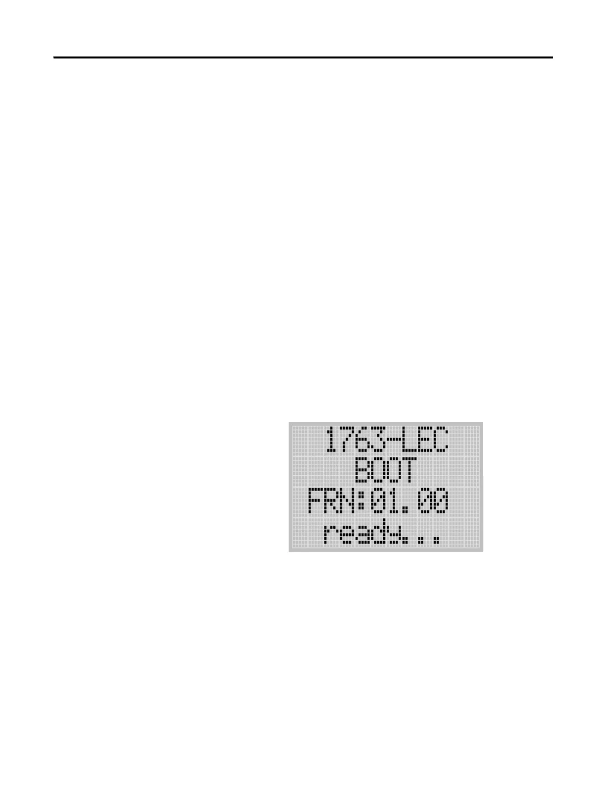
1. Controller mode and communications parameters are checked. The
screen as shown below is displayed on the LCD as well.
2. Download begins.

 Loading...


