Publication 1763-UM001E-EN-P - June 2015
Communication Connections 89
Connecting the AIC+
You can connect a MicroLogix 1100 controller to a DH-485 network via
Channel 0 directly without using an optical isolator, such as AIC+, catalog
number 1761-NET-AIC, because Channel 0 is isolated. However, you need to
use an AIC+ to connect your PC or other MicroLogix Family products, such
as MicroLogix 1200, to a DH-485 network.
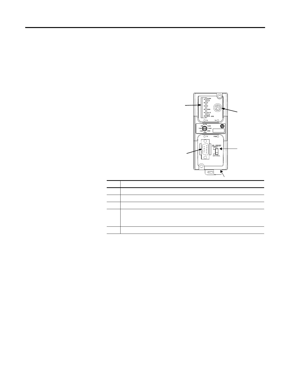
The following figure shows the external wiring connections and specifications
of the AIC+.
For additional information on connecting the AIC+, refer to the Advanced
Interface Converter (AIC+) User Manual, publication 1761-UM00.
Item Description
1 Port 1 - DB-9 RS-232, DTE
2 Port 2 - mini-DIN 8 RS-232 DTE
3 Port 3 - RS-485 Phoenix plug
4 DC Power Source selector switch
(cable = port 2 power source,
external = external power source connected to item 5)
5 Terminals for external 24V DC power supply and chassis ground
AIC+ Advanced Interface Converter
(1761-NET-AIC)
3
2
4
5
1

 Loading...


