EasyManuals Logo

Allen-Bradley MicroLogix 1100 User Manual

Allen-Bradley MicroLogix 1100
256 pages
To Next Page IconTo Next Page
To Previous Page IconTo Previous Page
Page #90 background imageLoading...
Page #90 background image
Publication 1763-UM001E-EN-P - June 2015
88 Communication Connections
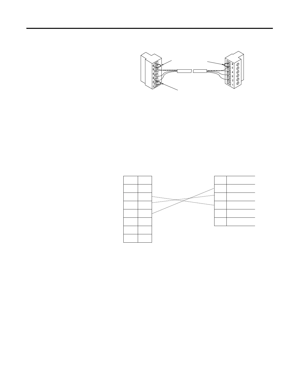
End-of-Line Termination
MicroLogix 1100 Channel 0 to DH-485 Communication Cable Pinout
When connecting MicroLogix 1100 Channel 0 to DH-485 communication
cable pinout using an RS-232 cable, the maximum that the cable length may be
extended is 15.24 m (50 ft). Refer to the following typical pinout:
Jumper
Jumper
Belden #3106A or #9842 Cable
1219 m (4000ft) Maximum
Jumper
DTE Device
(MicroLogix
1100
Channel 0)
DCE Device (DH-485
connector)
8-Pin 6-pin
7 TXD 6 Termination
4RXD 5A
2GND 4B
1 B(+) 3 Common
8 A(-) 2 Shield
5 N.C. 1 ChassisGround
6CTS
3RTS

Table of Contents

Other manuals for Allen-Bradley MicroLogix 1100

Questions and Answers:

Question and Answer IconNeed help?

Do you have a question about the Allen-Bradley MicroLogix 1100 and is the answer not in the manual?

Allen-Bradley MicroLogix 1100 Specifications

General IconGeneral
Processor32-bit
Programming SoftwareRSLogix 500
MountingDIN rail or panel mount
Power Supply24V DC
TypeCompact PLC
Digital Inputs12
Digital Outputs8
Analog Inputs4 (depending on model)
Analog OutputsOptional with expansion module
Programming LanguageLadder Logic
Operating Temperature0 to 55 °C (32 to 131 °F)
SeriesMicroLogix

Related product manuals