Publication 1763-UM001E-EN-P - June 2015
210 Connecting to Networks via RS-232/RS-485 Interface
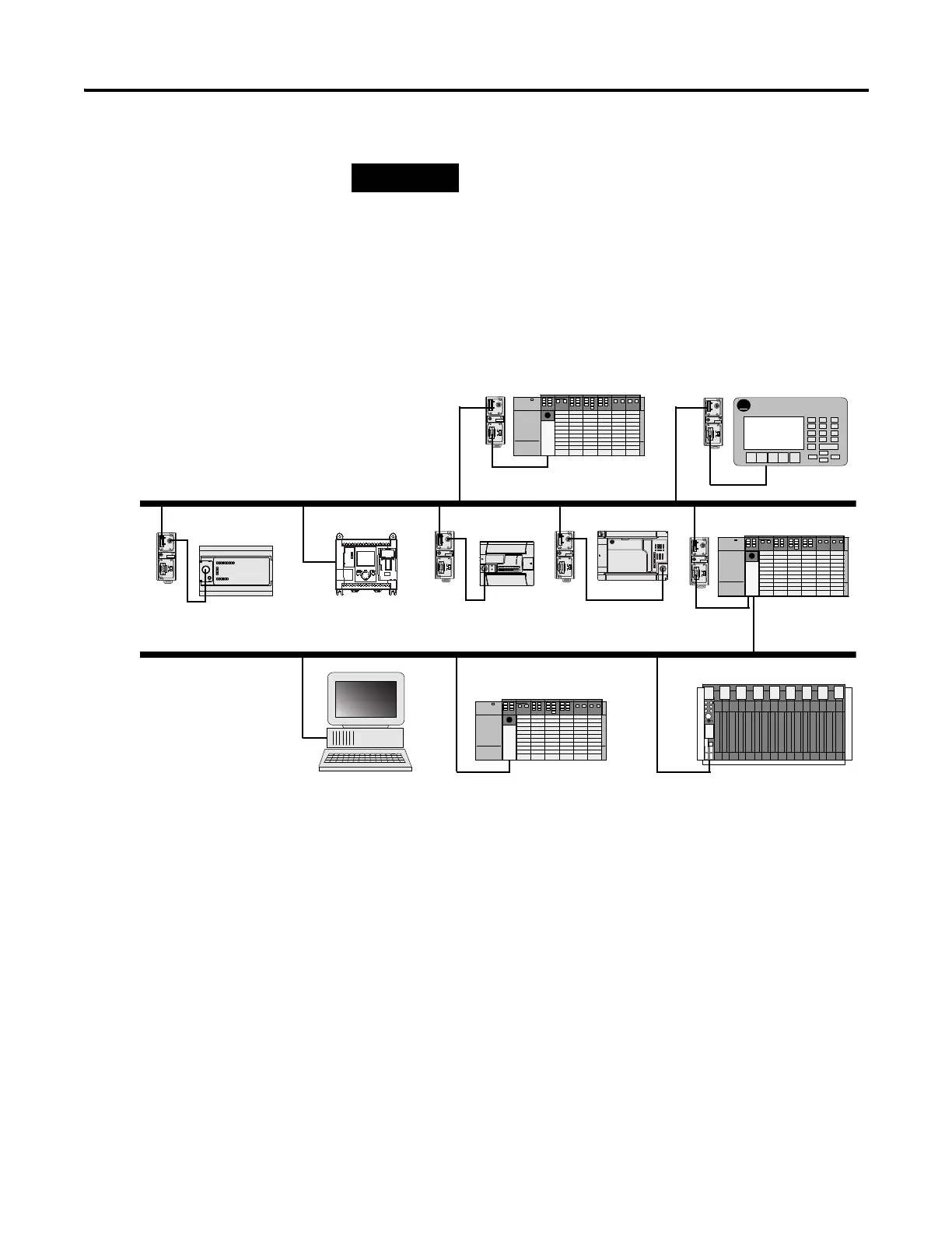
Example DH-485 Connections
The following network diagrams provide examples of how to connect
MicroLogix™ controllers to the DH-485 network. You can connect a
MicroLogix 1100 controller to your DH-485 network directly without using a
RS-232 to RS-485 converter and optical isolator, such as the Advanced
Interface Converter (AIC+), catalog number 1761-NET-AIC, as shown in the
illustrations below, because Channel 0 has isolation and RS-485 built-in.
However, you may need to use an AIC+ to connect other controllers to a
DH-485 network. For more information on the AIC+, see the Advanced
Interface Converter and DeviceNet Interface Installation Instructions,
Publication 1761-5.11.
Use a 1763-NC01 Series A or later cable to connect
a MicroLogix 1100 controller to a DH-485 network.
You can connect a MicroLogix 1100 controller to
your DH-485 network directly without using a
RS-232 to RS-485 converter and optical isolator, such
as the AIC+, catalog number 1761-NET-AIC, as
shown in the illustration below, because Channel 0
has isolation and RS-485 built-in.
A-B
PanelView
TERM
A
B
COM
SHLD
CHS GND
TX
TX PWR
TX
DC SOURCE
CABLE
EXTERNAL
TERM
A
B
COM
SHLD
CHS GND
TX
TX PWR
TX
DC SOURCE
CABLE
EXTERNAL
TERM
A
B
COM
SHLD
CHS GND
TX
TX PWR
TX
DC SOURCE
CABLE
EXTERNAL
TERM
A
B
COM
SHLD
CHS GND
TX
TX PWR
TX
DC SOURCE
CABLE
EXTERNAL
TERM
A
B
COM
SHLD
CHS GND
TX
TX PWR
TX
DC SOURCE
CABLE
EXTERNAL
TERM
A
B
COM
SHLD
CHS GND
TX
TX PWR
TX
DC SOURCE
CABLE
EXTERNAL
AIC+ AIC+ AIC+
AIC+
DH-485 Network
SLC 5/04
PanelView 550
MicroLogix 1500MicroLogix 1000 MicroLogix 1200
SLC 5/04
AIC+
AIC+
SLC 5/04 PLC-5
DH+ Network
Personal Computer
MicroLogix 1100

 Loading...


