Publication 1763-UM001E-EN-P - June 2015
180 Replacement Parts
Lithium Battery (1763-BA)
Installation
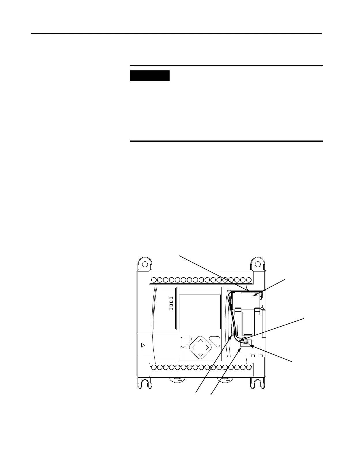
Follow the procedure below to ensure proper replaceable battery installation.
1. Insert a battery into the battery pocket with wires facing up.
2. Insert the battery wire connector into the battery connector.
3. Secure the battery connector wires along the wire guide, as shown
below.
When the controller’s Battery Low indicator is lit, check
whether the battery wire connector is connected correctly
or replace the replaceable battery with a new one
immediately. When the indicator turns on, it means that
either the battery is disconnected, or that the battery
requires replacement. The controller is designed to operate
for up to 2 weeks, from the time that the indicator first
turns on. We recommend that you replace the battery
immediately when the indicator turns on.
Wire Guide
Battery Wires
Replaceable
Battery
Replaceable Battery Pocket
Battery Wire
Connector
Battery Connector

 Loading...


