Publication 1763-UM001E-EN-P - June 2015
Installing Your Controller 35
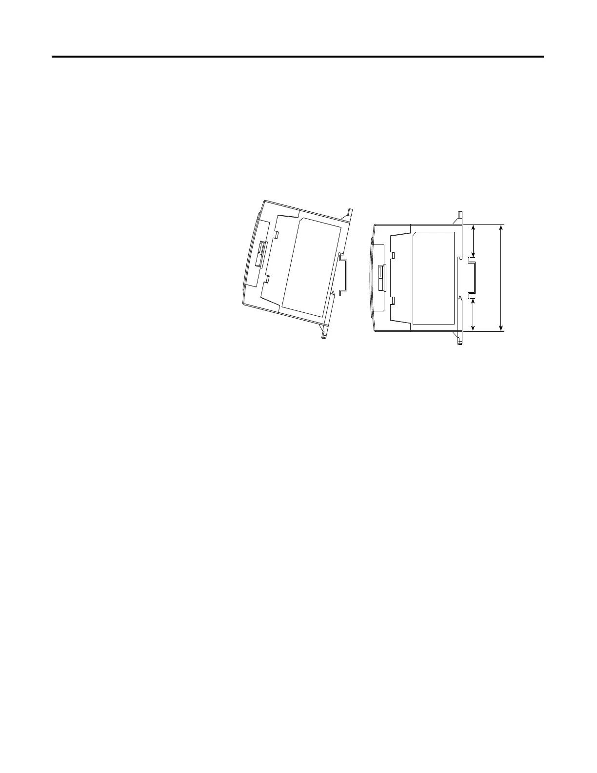
DIN Rail Mounting
The maximum extension of the latch is 14 mm (0.55 in.) in the open position.
A flat-blade screwdriver is required for removal of the controller. The
controller can be mounted to EN50022-35x7.5 or EN50022-35x15 DIN rails.
DIN rail mounting dimensions are shown below.
Follow this procedure to install your controller on the DIN rail.
1. Mount your DIN rail. (Make sure that the placement of the controller
on the DIN rail meets the recommended spacing requirements,
see Controller and Expansion I/O Spacing on page 33. Refer to the
mounting template inside the back cover of this document.)
2. Close the DIN latch, if it is open.
3. Hook the top slot over the DIN rail.
4. While pressing the controller down against the top of the rail, snap the
bottom of the controller into position.
5. Leave the protective debris shield attached until you are finished wiring
the controller and any other devices.
To remove your controller from the DIN rail:
1. Place a flat-blade screwdriver in the DIN rail latch at the bottom of the
controller.
2. Holding the controller, pry downward on the latch until the latch locks
in the open position.
3. Repeat steps 1 and 2 for the second DIN rail latch.
4. Unhook the top of the DIN rail slot from the rail.
27.5 mm
(1.08 in.)
27.5 mm
(1.08 in.)
90 mm
(3.5 in.)

 Loading...


