EasyManuals Logo

Allen-Bradley MicroLogix 1100 User Manual

Allen-Bradley MicroLogix 1100
256 pages
To Next Page IconTo Next Page
To Previous Page IconTo Previous Page
Page #234 background imageLoading...
Page #234 background image
Publication 1763-UM001E-EN-P - June 2015
232 System Loading and Heat Dissipation
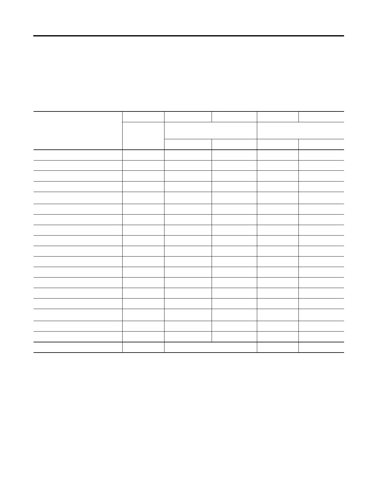
System Loading Example Calculations
Current Loading
Calculating the Current for Expansion I/O
Catalog Number
(1)
n A B n x A n x B
Number of
Modules
Device Current Requirements
(max)
Calculated Current
at 5V DC (mA) at 24V DC (mA) at 5V DC (mA) at 24V DC (mA)
1762-IA8 2 50 0 100 0
1762-IF4 40 50
1762-IF2OF2 40 105
1762-IQ8 50 0
1762-IQ16
70
(2)
0
1762-IQ32T 170 0
1762-IR4 40 50
1762-IT4 40 50
1762-OA8 115 0
1762-OB8 115 0
1762-OB16 175 0
1762-OB32T 175 0
1762-OF4 40 165
1762-OV32T 175 0
1762-OW8 2 80 90 160 180
1762-OW16
140
(2)
180
(2)
1762-OX6I 110 110
1762-IQ8OW6 110 80
Total Modules (4 maximum): 4 Subtotal: 260 180
(1) Refer to your expansion I/O Installation Instructions for Current Requirements not listed in this table.
(2) Only applicable to Series B I/O modules.

Table of Contents

Other manuals for Allen-Bradley MicroLogix 1100

Questions and Answers:

Question and Answer IconNeed help?

Do you have a question about the Allen-Bradley MicroLogix 1100 and is the answer not in the manual?

Allen-Bradley MicroLogix 1100 Specifications

General IconGeneral
Processor32-bit
Programming SoftwareRSLogix 500
MountingDIN rail or panel mount
Power Supply24V DC
TypeCompact PLC
Digital Inputs12
Digital Outputs8
Analog Inputs4 (depending on model)
Analog OutputsOptional with expansion module
Programming LanguageLadder Logic
Operating Temperature0 to 55 °C (32 to 131 °F)
SeriesMicroLogix

Related product manuals