EasyManuals Logo

Allen-Bradley MicroLogix 1100 User Manual

Allen-Bradley MicroLogix 1100
256 pages
To Next Page IconTo Next Page
To Previous Page IconTo Previous Page
Page #39 background imageLoading...
Page #39 background image
Publication 1763-UM001E-EN-P - June 2015
Installing Your Controller 37
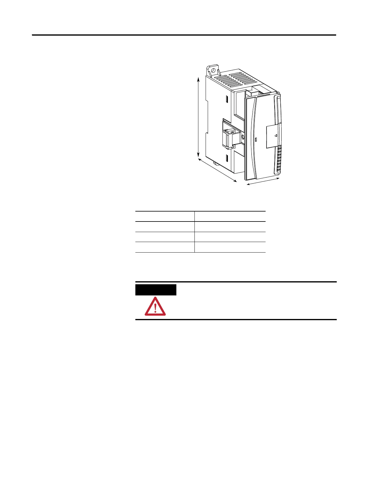
1762 Expansion I/O
Dimensions
Mounting 1762 Expansion
I/O
DIN Rail Mounting
The module can be mounted using the following DIN rails:
35 x 7.5 mm (EN 50 022 - 35 x 7.5), or
35 x 15 mm (EN 50 022 - 35 x 15).
Before mounting the module on a DIN rail, close the DIN rail latch. Press the
DIN rail mounting area of the module against the DIN rail. The latch
momentarily opens and locks into place.
Dimension Expansion I/O Module
A 90 mm (3.5 in.)
B 40 mm (1.57 in.)
C 87 mm (3.43 in.)
A
B
C
ATTENTION
During panel or DIN rail mounting of all devices, be sure
that all debris (metal chips, wire stands, etc.) is kept from
falling into the module. Debris that falls into the module
could cause damage when the module is under power.

Table of Contents

Other manuals for Allen-Bradley MicroLogix 1100

Questions and Answers:

Question and Answer IconNeed help?

Do you have a question about the Allen-Bradley MicroLogix 1100 and is the answer not in the manual?

Allen-Bradley MicroLogix 1100 Specifications

General IconGeneral
Processor32-bit
Programming SoftwareRSLogix 500
MountingDIN rail or panel mount
Power Supply24V DC
TypeCompact PLC
Digital Inputs12
Digital Outputs8
Analog Inputs4 (depending on model)
Analog OutputsOptional with expansion module
Programming LanguageLadder Logic
Operating Temperature0 to 55 °C (32 to 131 °F)
SeriesMicroLogix

Related product manuals