Publication 1763-UM001E-EN-P - June 2015
Communication Connections 87
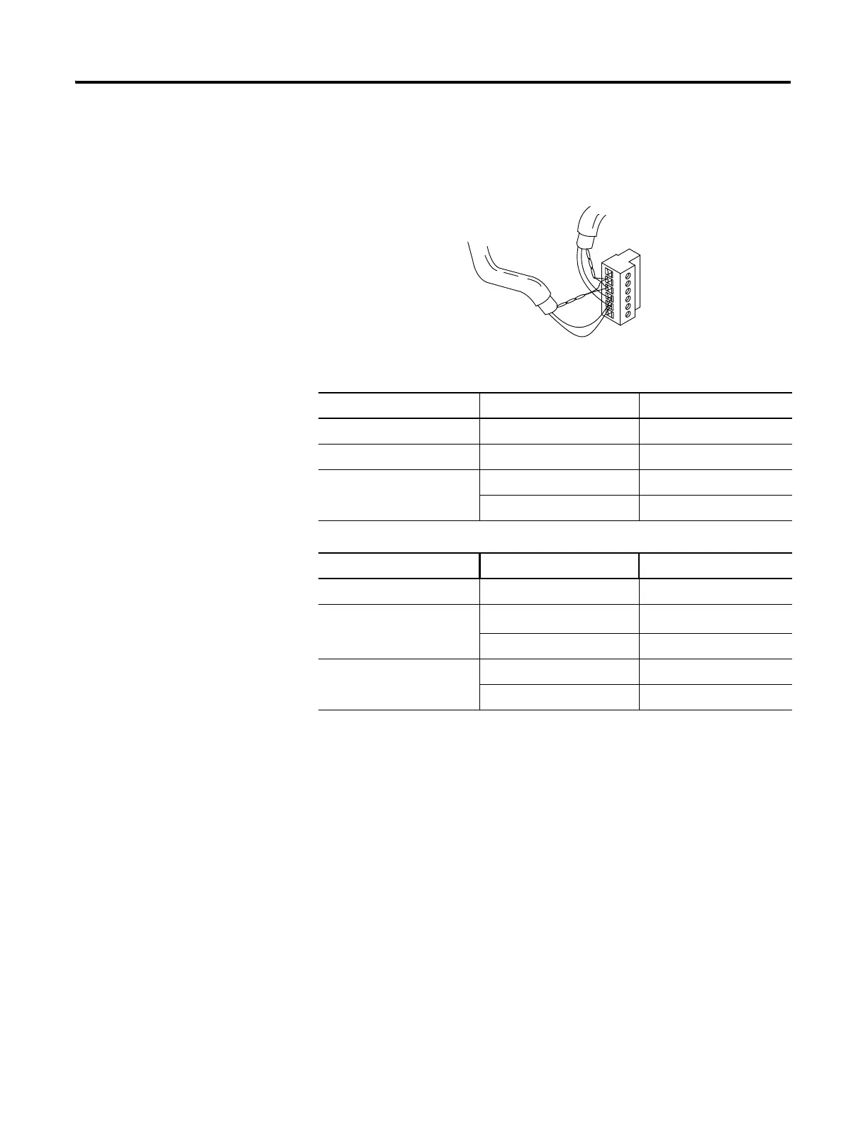
Multiple Cable Connection
When connecting multiple cables to the DH-485 connector, use the following
diagram.
Grounding and Terminating the DH-485 Network
Only one connector at the end of the link must have Terminals 1 and 2
jumpered together. This provides an earth ground connection for the shield of
the communication cable.
Both ends of the network must have Terminals 5 and 6 jumpered together, as
shown below. This connects the termination impedance (of 120 ohm) that is
built into each AIC+ or the 1763-NC01 cable as required by the DH-485
specification.
Connections using Belden #3106A Cable
For this Wire/Pair Connect this Wire To this Terminal
Shield/Drain Non-jacketed Terminal 2 - Shield
Blue Blue Terminal 3 - (Common)
White/Orange White with Orange Stripe Terminal 4 - (Data B)
Orange with White Stripe Terminal 5 - (Data A)
Connections using Belden #9842 Cable
For this Wire/Pair Connect this Wire To this Terminal
Shield/Drain Non-jacketed Terminal 2 - Shield
Blue/White White with Blue Stripe
Cut back - no connection
(1)
(1)
To prevent confusion when installing the communication cable, cut back the white with blue stripe wire
immediately after the insulation jacket is removed. This wire is not used by DH-485.
Blue with White Stripe Terminal 3 - (Common)
White/Orange White with Orange Stripe Terminal 4 - (Data B)
Orange with White Stripe Terminal 5 - (Data A)
to Next Device
to Previous Device

 Loading...


