Publication 1763-UM001E-EN-P - June 2015
Using the LCD 111
Monitoring a Bit File
For explanations in this section, we assume the followings in the application
program:
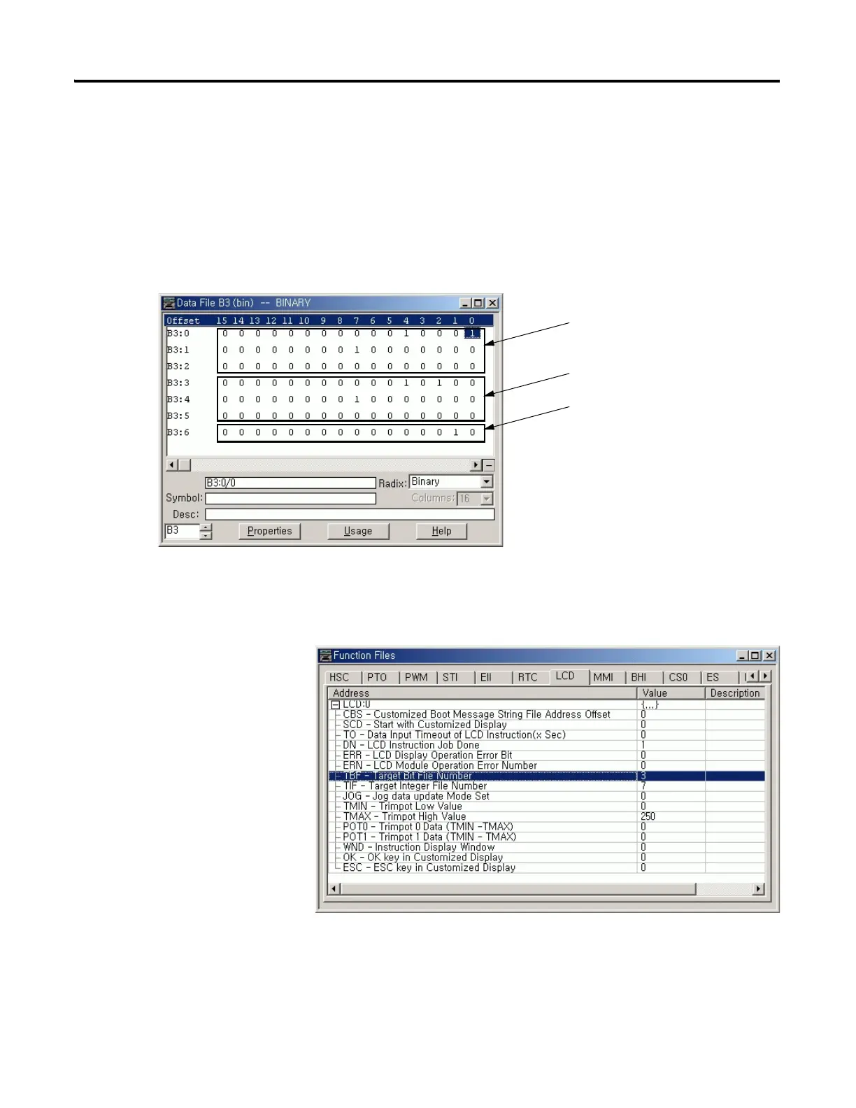
• A bit file B3, which is 7 elements long (7 words = 112 bits), is defined
with the preset data, as shown in the screen capture below.
• The TBF element of the LCD Function File is set to 3 to specify the bit
file B3 as the target bit file to monitor on the LCD, as shown in the
screen capture below.
• The controller mode is set to REMOTE RUN.
data bits (first 48 bits), which
are monitored on the LCD
and maskable by protection bits
protection bits (second 48 bits)
data bits (after the first 96 bits), which
are not monitored on the LCD and not
maskable by protection bits

 Loading...


