Publication 1763-UM001E-EN-P - June 2015
90 Communication Connections
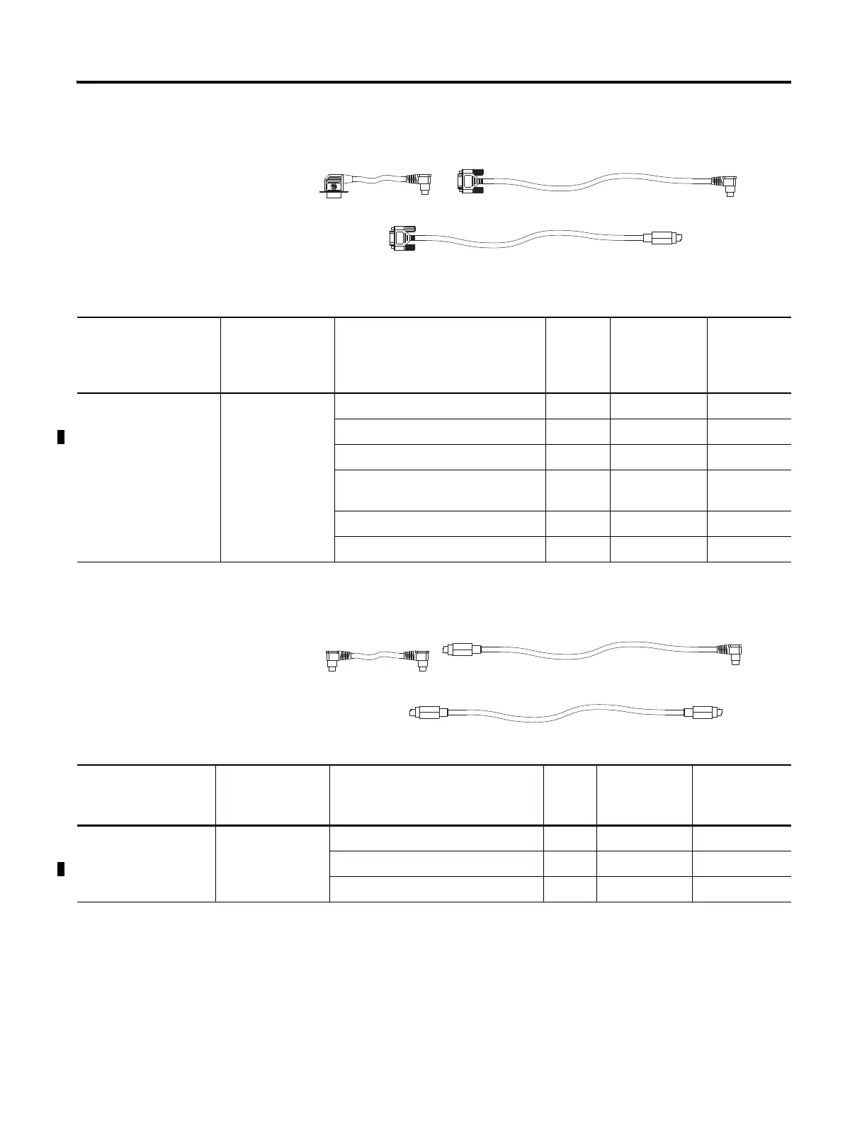
Cable Selection Guide
1761-CBL-PM02
(2)
1761-CBL-AP00
(2)
1761-CBL-PH02
Cable Length Connections from to AIC+ External
Power Supply
Required
(1)
Power
Selection
Switch
Setting
(1)
1761-CBL-AP00
(2)
1761-CBL-PM02
(2)
1761-CBL-PH02
45 cm (17.7 in.)
2 m (6.5 ft)
2 m (6.5 ft)
SLC 5/03 or SLC 5/04 processors, ch 0 port 2 yes external
MicroLogix™ 1000, 1200, or 1500 ch 0 port 1 yes external
MicroLogix™ 1100 ch 0 port 1 yes external
PanelView 550 through NULL modem
adapter
port 2 yes external
DTAM Plus / DTAM Micro port 2 yes external
PC COM port port 2 yes external
(1)
External power supply required unless the AIC+ is powered by the device connected to port 2, then the selection switch should be set to cable.
(2)
Series C or later cables are required.
1761-CBL-HM02
(2)
1761-CBL-AM00
(2)
1761-CBL-AH02
Cable Length Connections from to AIC+ External
Power Supply
Required
(1)
Power
Selection
Switch Setting
1761-CBL-AM00
(2)
1761-CBL-HM02
(2)
1761-CBL-AH02
45 cm (17.7 in.)
2 m (6.5 ft)
2 m (6.5 ft)
MicroLogix™ 1000, 1200, or 1500 ch 0 port 2 no cable
MicroLogix™ 1100 ch 0 port 2 Yes external
to port 2 on another AIC+ port 2 yes external
(1)
External power supply required unless the AIC+ is powered by the device connected to port 2, then the selection switch should be set to cable.
(2)
Series C or later cables are required.

 Loading...


