Publication 1763-UM001E-EN-P - June 2015
Using the LCD 103
:
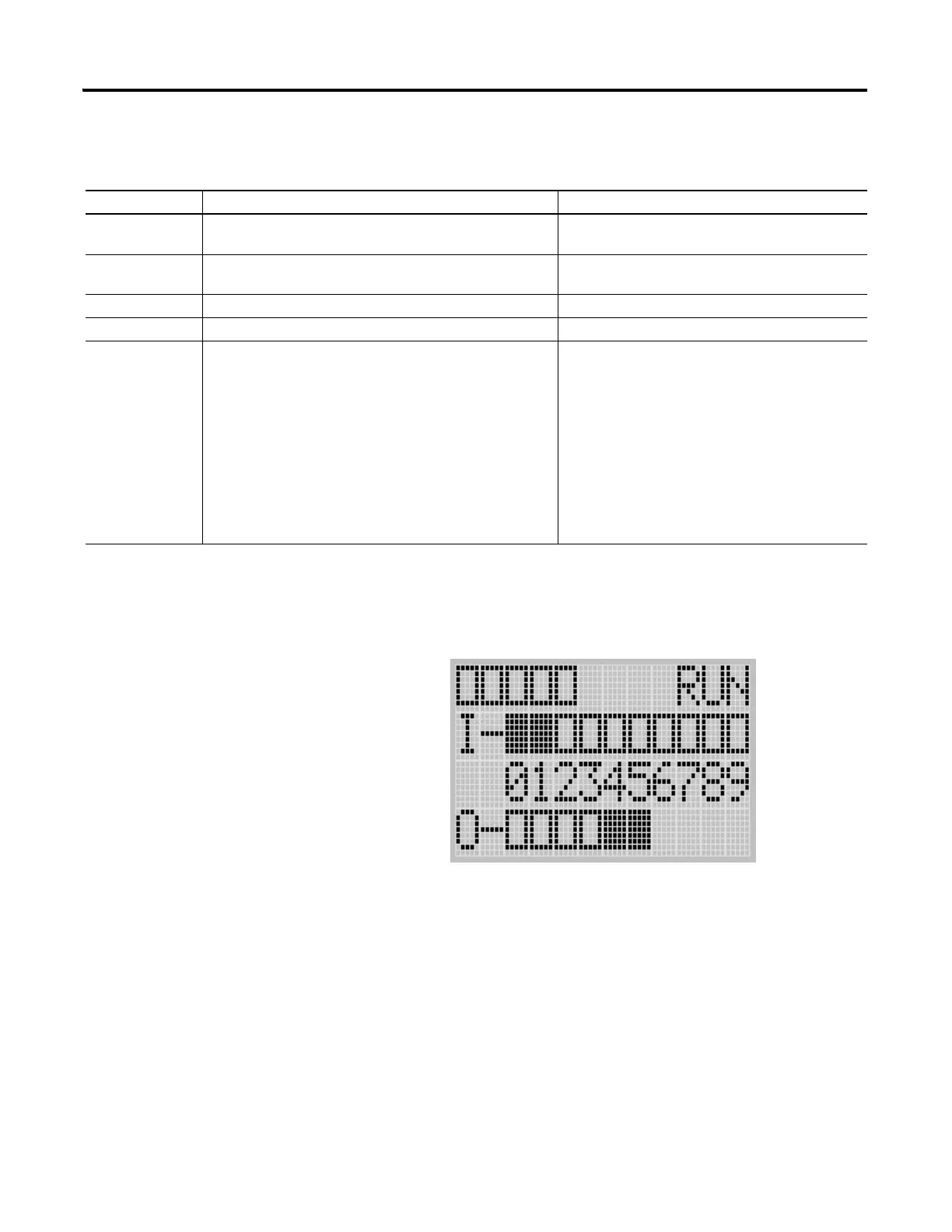
LCD Default Screen - I/O Status Screen
.
This is the default screen of the display, allowing you to monitor controller and
I/O Status. For more information on the I/O Status screen, see I/O Status
on page 5-107.
Main Menu Items
Menu Item Description For details, refer to
I/O Status Displays the I/O Status screen, which shows the I/O status
of the embedded digital I/O.
I/O Status on page 5-107
Monitoring Allows you to view and change the data value of a bit and an
integer file.
Monitoring Bit File on page 5-109
Monitoring Integer File on page 5-115
Mode Switch Allows you to change the mode switch selection. Using the Mode Switch on page 5-122
User Displ Displays the user defined LCD screen Using a User Defined LCD Screen on page 5-126
Advance Set Allows you to configure or view the following:
• Change the key in mode for value entry for a trim pot.
• Use the communications toggle functionality.
• View the Ethernet port configuration.
• Change the data value of trim pots.
• View system information, such as OS series and
firmware version.
• Changing Key In Mode on page 5-128
• Using Communications Toggle Functionality
on page 5-131
• Viewing Ethernet Port Configuration on
page 5-131
• Using Trim Pots on page 5-133
• I/O Status on page 5-107
COM
M
0
COMM1
DCOMM
BAT. LO
U-MSG

 Loading...


