Publication 1763-UM001E-EN-P - June 2015
116 Using the LCD
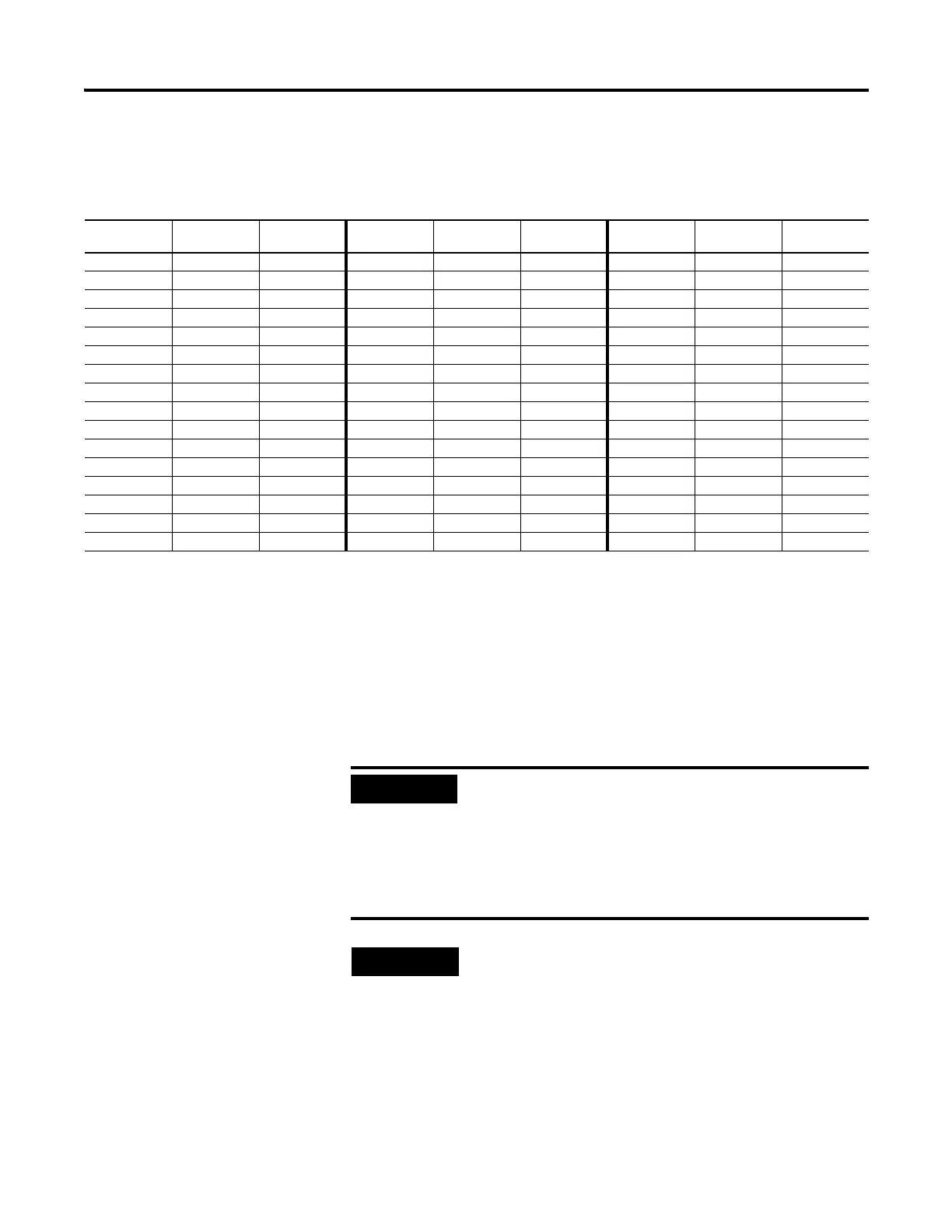
The example table below shows how the LCD uses the configuration
information with integer file number 7 (LCD:0.TIF=7).
The element number displayed on the LCD corresponds to the data address as
illustrated in the table. The protection bit defines whether the data is editable
or read-only. When the protection bit is set (1), the corresponding data address
is considered read-only by the LCD. The “Protected!” message is displayed
whenever a read-only element is active on the LCD. When the protection bit is
clear (0) or the protection bit does not exist, no additional message is displayed
and the data within the corresponding address is editable from the LCD
keypad.
Element
Number
Data Address Protection Bit Element
Number
Data Address Protection Bit Element
Number
Data Address Protection Bit
0 N7:0 N7:48/0 16 N7:16 N7:49/0 32 N7:32 N7:50/0
1 N7:1 N7:48/1 17 N7:17 N7:49/1 33 N7:33 N7:50/1
2 N7:2 N7:48/2 18 N7:18 N7:49/2 34 N7:34 N7:50/2
3 N7:3 N7:48/3 19 N7:19 N7:49/3 35 N7:35 N7:50/3
4 N7:4 N7:48/4 20 N7:20 N7:49/4 36 N7:36 N7:50/4
5 N7:5 N7:48/5 21 N7:21 N7:49/5 37 N7:37 N7:50/5
6 N7:6 N7:48/6 22 N7:22 N7:49/6 38 N7:38 N7:50/6
7 N7:7 N7:48/7 23 N7:23 N7:49/7 39 N7:39 N7:50/7
8 N7:8 N7:48/8 24 N7:24 N7:49/8 40 N7:40 N7:50/8
9 N7:9 N7:48/9 25 N7:25 N7:49/9 41 N7:41 N7:50/9
10 N7:10 N7:48/10 26 N7:26 N7:49/10 42 N7:42 N7:50/10
11 N7:11 N7:48/11 27 N7:27 N7:49/11 43 N7:43 N7:50/11
12 N7:12 N7:48/12 28 N7:28 N7:49/12 44 N7:44 N7:50/12
13 N7:13 N7:48/13 29 N7:29 N7:49/13 45 N7:45 N7:50/13
14 N7:14 N7:48/14 30 N7:30 N7:49/14 46 N7:46 N7:50/14
15 N7:15 N7:48/15 31 N7:31 N7:49/15 47 N7:47 N7:50/15
Although the LCD does not allow protected data to
be changed from its keypad, the control program or
other communication devices do have access to this
data. Protection bits do not provide any overwrite
protection to data within the target integer file. It is
entirely the user’s responsibility to ensure that data is
not inadvertently overwritten.
• Remaining addresses within the target file can be
used without restrictions (addresses N7:51 and
above, in this example).
• The LCD always starts at word 0 of a data file. It
cannot start at any other address within the file.

 Loading...


