EasyManuals Logo

Allen-Bradley MicroLogix 1100 User Manual

Allen-Bradley MicroLogix 1100
256 pages
To Next Page IconTo Next Page
To Previous Page IconTo Previous Page
Page #172 background imageLoading...
Page #172 background image
Publication 1763-UM001E-EN-P - June 2015
170 Specifications
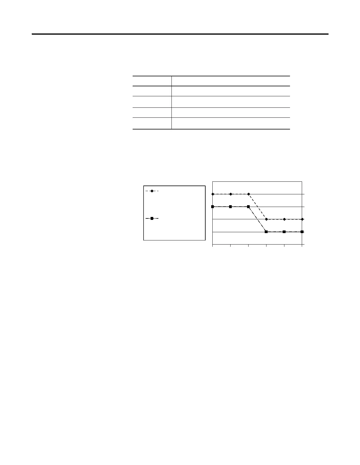
Relays Used vs. Maximum Current per Relay (24V DC) 1762-OX6I
Module Load Ratings 1762-OX6I
Volts (max.) Controlled Load (Current) per Module (max.)
240V AC 6 A
120V AC
12 A
(1)
(1) Current per relay limited to 6 A at ambient temperatures above 40 °C (104.°F).
125V DC 11.5 A
24V DC
30 A
(2)
(2) 24 A in ambient temperatures above 40 °C (104.°F). Limited by ambient temperature and
the number of relays controlling loads. See below.
123
3
4
5
6
7
8
45 6
Number of Relays Controlling Loads
Maximum Current per Relay (Amps)
Ambient Temperature
below 40 °C (104.°F)
Ambient Temperature
above 40 °C (104.°F)

Table of Contents

Other manuals for Allen-Bradley MicroLogix 1100

Questions and Answers:

Question and Answer IconNeed help?

Do you have a question about the Allen-Bradley MicroLogix 1100 and is the answer not in the manual?

Allen-Bradley MicroLogix 1100 Specifications

General IconGeneral
Processor32-bit
Programming SoftwareRSLogix 500
MountingDIN rail or panel mount
Power Supply24V DC
TypeCompact PLC
Digital Inputs12
Digital Outputs8
Analog Inputs4 (depending on model)
Analog OutputsOptional with expansion module
Programming LanguageLadder Logic
Operating Temperature0 to 55 °C (32 to 131 °F)
SeriesMicroLogix

Related product manuals